PowerFlex 700 Technical Data
20B-TD001F-EN-P 27
Frames 7…10
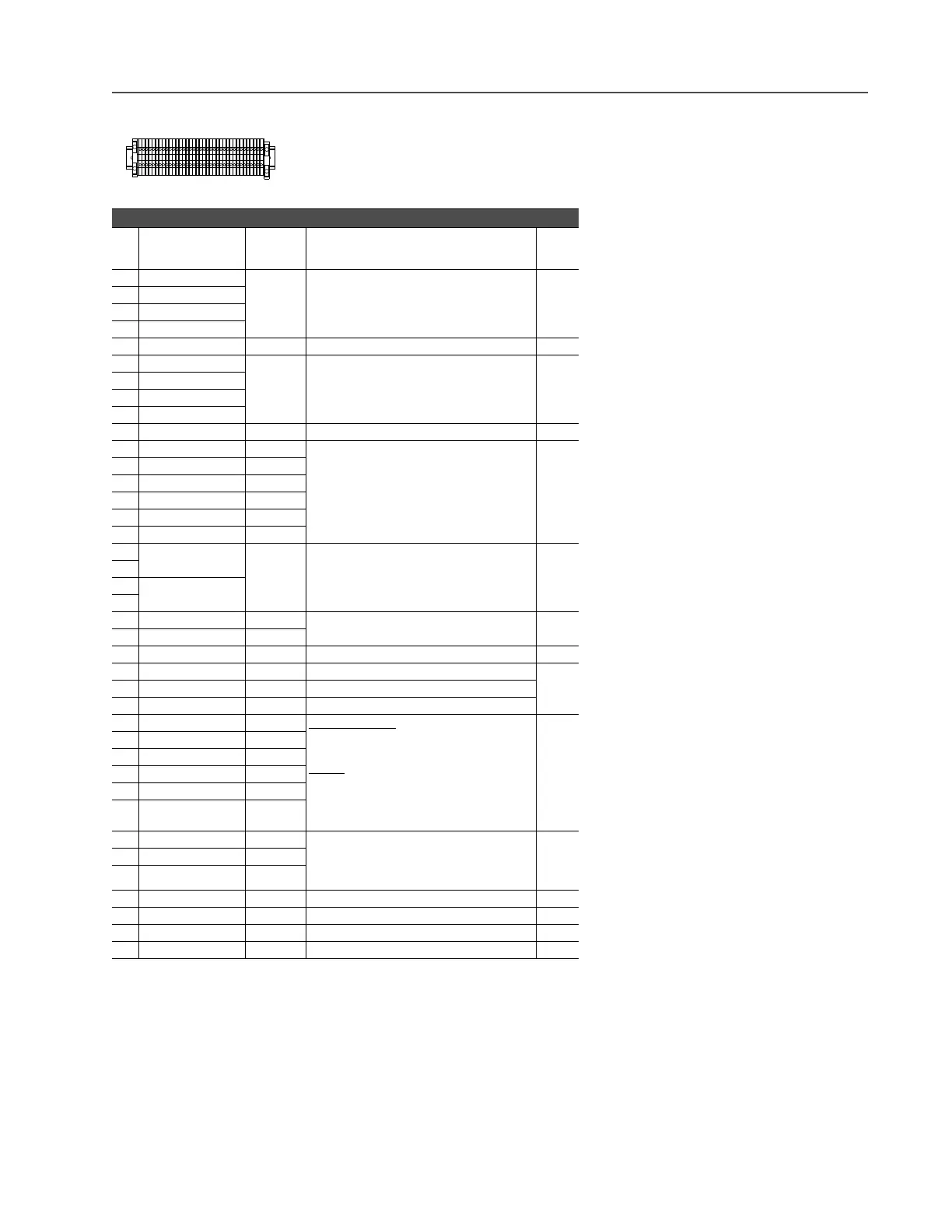
Vector Control Option (Frames 7…10)
No. Signal
Factory
Default
Description
Related
Param.
1 Analog In 1 (–)
(1)
(1)
Important: 0-20mA operation requires a jumper at terminals 17 & 18 (or 19 & 20). Drive damage may occur if
jumper is not installed.
(2)
(2)
These inputs/outputs are dependant on a number of parameters (see “Related Parameters”).
Isolated
(3)
, bipolar, differential, ±10V/4-20mA, 11
bit & sign, 88k ohm input impedance. For 4-20mA,
a jumper must be installed at terminals 17 & 18 (or
19 & 20).
(3)
Differential Isolation - External source must be maintained at less than 160V with respect to PE. Input provides
high common mode immunity.
320 -
327
2 Analog In 1 (+)
(1)
3 Analog In 2 (–)
(1)
4 Analog In 2 (+)
(1)
5 Pot Common – For (+) and (–) 10V pot references.
6 Analog Out 1 (–)
(2)
Bipolar (current output is not bipolar), ±10V/4-
20mA, 11 bit & sign, voltage mode - limit current to
5 mA. Current mode - max. load resistance is 400
ohms.
340 -
347
7 Analog Out 1 (+)
8 Analog Out 2 (–)
9 Analog Out 2 (+)
10 HW PTC Input 1 – 1.8k ohm PTC, Internal 3.32k ohm pull-up resistor 238 259
11 Digital Out 1 – N.C.
(4)
(4)
Contacts in unpowered state. Any relay programmed as Fault or Alarm will energize (pick up) when power is
applied to drive and deenergize (drop out) when a fault or alarm exists. Relays selected for other functions will
energize only when that condition exists and will deenergize when condition is removed.
Fault Max. Resistive Load:
240V AC/30V DC – 1200VA, 150W
Max. Current: 5A, Min. Load: 10mA
Max. Inductive Load:
240V AC/30V DC – 840VA, 105W
Max. Current: 3.5A, Min. Load: 10mA
380 -
391
12 Digital Out 1 Common
13 Digital Out 1 – N.O.
(4)
NOT Fault
14 Digital Out 2 – N.C.
(4)
NOT Run
15 Digital Out 2/3 Com.
16 Digital Out 3 – N.O.
(4)
Run
17 Current In Jumper
(1)
–
Analog In 1
Placing a jumper across terminals 17 & 18 (or 19
& 20) will configure that analog input for current.
18
19 Current In Jumper
(1)
–
Analog In 2
20
21 –10V Pot Reference – 2k ohm minimum load.
22 +10V Pot Reference –
23 HW PTC Input 2 – See above
24 +24VDC
(5)
– Drive supplied logic input power.
(5)
(5)
150mA maximum Load. Not present on 115V versions.
25 Digital In Common –
26 24V Common
(5)
– Common for internal power supply.
27 Digital In 1 Stop - CF 115V AC, 50/60 Hz
- Opto isolated
Low State: less than 30V AC
High State: greater than 100V AC
24V DC
- Opto isolated
Low State: less than 5V DC
High State: greater than 20V DC
11.2 mA DC
361 -
366
28 Digital In 2 Start
29 Digital In 3 Auto/Man.
30 Digital In 4 Speed Sel 1
31 Digital In 5 Speed Sel 2
32 Digital In 6/Hardware
Enable, see pg. 28
Speed Sel 3
33 Digital Out 4 – N.C. Fault Dedicated fault output - Not user configurable.
Relay will energize (pick up) when power is
applied to drive and deenergize (drop out) when a
fault exists. See Terminals 11…16 for specs.
34 Digital Out 4 Common
35 Digital Out 4 – N.O. NOT Fault
PS+ Aux. Control Power (+)
PS- Aux. Control Power (-)
PE PE Ground PE Ground
PE PE Ground PE Ground
1

 Loading...


