PowerFlex 700 Technical Data
28 20B-TD001F-EN-P
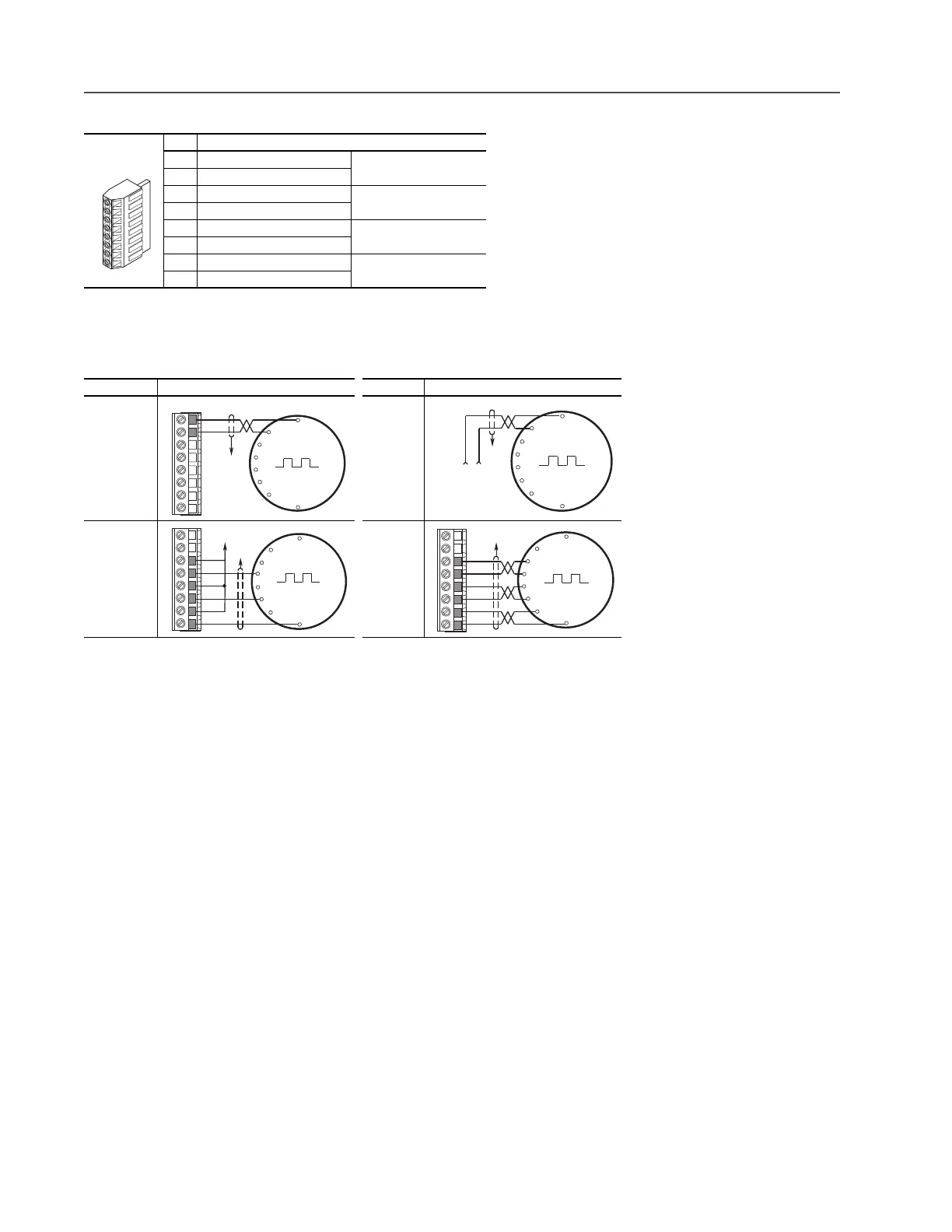
Encoder Terminal Block (Vector Control Option Only)
Sample Encoder Wiring
Hardware Enable Circuitry (Vector Control Option Only)
By default, the user can program a digital input as an Enable input. The status of this input is interpreted by drive software.
If the application requires the drive to be disabled without software interpretation, a “dedicated” hardware enable
configuration can be utilized. This is done by removing a jumper and wiring the enable input to “Digital In 6”.
No. Description (refer to page 73 for encoder specifications)
8+12V
(1)
DC Power
(1)
Jumper selectable +5/12V is available on 20B-ENC-1 Encoder Boards.
Internal power source
250 mA.
7+12V
(1)
DC Return (Common)
6 Encoder Z (NOT) Pulse, marker or registration
input.
(2)
(2)
Z channel can be used as a pulse input while A & B are used for encoder.
5 Encoder Z
4 Encoder B (NOT) Quadrature B input.
3 Encoder B
2 Encoder A (NOT) Single channel or
quadrature A input.
1 Encoder A
I/O Connection Example I/O Connection Example
Encoder
Power –
(1)
Internal
Drive Power
Internal (drive)
12V DC,
250mA
(1)
SHLD connection is on drive chassis (see page 19).
Encoder
Power –
External
Power
Source
Encoder
Signal –
Single-Ended,
Dual Channel
Encoder
Signal –
Differential,
Dual
Channel
8
1
Common
+12V DC
(250 mA)
1
2
3
4
5
6
7
8
to SHLD
(1)
+
Common
External
Power
Supply
to
SHLD
(1)
B
B NOT
A NOT
A
Z
Z NOT
to SHLD
(1)
to Power Supply
Common
1
2
3
4
5
6
7
8
to SHLD
(1)
1
2
3
4
5
6
7
8
B
Z
A NOT
B NOT
Z NOT
A

 Loading...


