PowerFlex 700 Technical Data
20B-TD001F-EN-P 29
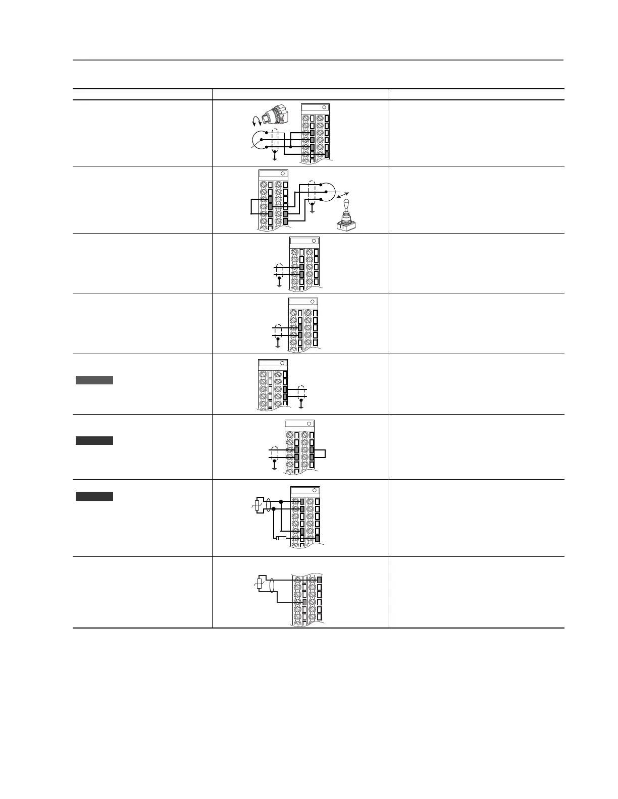
I/O Wiring Examples – Standard & Vector Control Options
Input/Output Connection Example Required Parameter Changes
Potentiometer Unipolar Speed Reference
(1)
10k Ohm Pot. Recommended
(2k Ohm Minimum)
(1)
Refer to the PowerFlex 700 User Manual for important bipolar wiring information.
• Adjust Scaling:
Parameters 91/92 and 325/326
• View Results:
Parameter 002
Joystick Bipolar Speed Reference
(1)
±10V Input
• Set Direction Mode:
Parameter 190 = “1, Bipolar”
• Adjust Scaling:
Parameters 91/92 and 325/326
• View Results:
Parameter 002
Analog Input Bipolar Speed Reference
±10V Input
• Set Direction Mode:
Parameter 190 = “1, Bipolar”
• Adjust Scaling:
Parameters 91/92 and 325/326
• View Results:
Parameter 002
Analog Voltage Input Unipolar Speed
Reference
0 to +10V Input
• Configure Input with parameter 320
• Adjust Scaling:
Parameters 91/92 and 325/326
• View results:
Parameter 002
Analog Current Input Unipolar Speed
Reference
4-20 mA Input
• Configure Input for Current:
Parameter 320, Bit 1 = “1, Current”
• Adjust Scaling:
Parameters 91/92 and 325/326
• View Results:
Parameter 002
Analog Current Input Unipolar Speed
Reference
0-20 mA Input
• Configure Input for Current:
Parameter 320 and add jumper at appropriate terminals
• Adjust Scaling:
Parameters 91/92 and 325/326
• View results:
Parameter 002
Analog Input, PTC
PTC OT set > 5V
PTC OT cleared < 4V
PTC Short < 0.2V
• Set Fault Config 1:
Parameter 238, bit 7 = “Enabled”
• Set Alarm Config 1:
Parameter 259, bit 11 = “Enabled”
• View Drive Alarm 1:
Parameter 211, bit 11 = “True”
HW PTC Input
Series B Only
PTC OT set > 5V
PTC OT cleared < 4V
PTC Short < 0.2V
• Set Fault Config 1:
Parameter 238, bit 13 = “Enabled”
• Set Alarm Config 1:
Parameter 259, bit 18 = “Enabled”
• View Status: Drive Alarm 1:
Parameter 211, bit 18 = “True”
3
4
5
22
3
5
21
22
3
4
Common
+
3
4
Common
+
Standard
19
20
Common
+
Vector
3
4
19
20
Common
+
Vector
5
3.32k
Ohm
1.8k
PTC
Ferrite
Bead
1
2
22
1.8k
PTC
Ferrite
Bead
10
23

 Loading...


