PowerFlex 700 Technical Data
30 20B-TD001F-EN-P
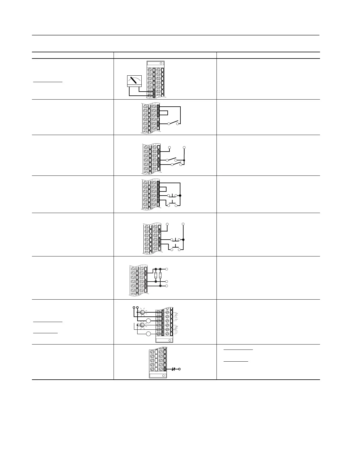
Input/Output Connection Example Required Parameter Changes
Analog Output
±10V, 0-20 mA Bipolar
+10V Unipolar (shown)
Standard Control
4-20 mA Unipolar
(use term. 8 & 9)
• Configure with Parameter 340
• Select Source Value:
Parameter 384, [Digital Out1 Sel]
• Adjust Scaling:
Parameters 343/344
2-Wire Control Non-Reversing
(1)
24V DC internal supply
(1)
Important: Programming inputs for 2 wire control deactivates all HIM Start buttons.
• Disable Digital Input:#1:
Parameter 361 = “0, Unused”
• Set Digital Input #2:
Parameter 362 = “7, Run”
• Set Direction Mode:
Parameter 190 = “0, Unipolar”
2-Wire Control
Reversing
(1)
External supply
(I/O Board dependent)
• Set Digital Input:#1:
Parameter 361 = “8, Run Forward”
• Set Digital Input #2:
Parameter 362 = “9, Run Reverse”
3-Wire Control
Internal supply
• No Changes Required
3-Wire Control
External supply
(I/O Board dependent). Requires 3-wire func-
tions only ([Digital In1 Sel]). Using 2-wire
selections will cause a type 2 alarm.
• No Changes Required
Digital Input
PLC Output Card (Board dependent).
• No Changes Required
Digital Output
Relays shown in powered state with drive
faulted. See page 26.
Standard Control
1 relay at terminals 14-16.
Vector Control
2 relays at terminals 14-16.
• Select Source to Activate:
Parameters 380/384
Enable Input • Standard Control
Configure with parameter 366
• Vector Control
Configure with parameter 366
For dedicated hardware Enable:
Remove Jumper J10 (see page 28)
6
7
+–
24
25
26
28
Stop-Run
25
27
28
Run Rev.
Run Fwd.
115V
+24V
Neutral/
Common
Start
24
25
26
27
28
Stop
Start
25
27
28
Stop
115V
+24V
Neutral/
Common
25
27
28
Control from
Prog. Controlle
Neutral/
Common
10k Ohm, 2 Watt
Power Source
11
12
13
14
15
16
Fault
NOT Fault
NOT Run
Run
or
32

 Loading...


