10 SLC 500 BASIC and BASIC-T Modules
Publication 1746-IN009B-EN-P - August 2005
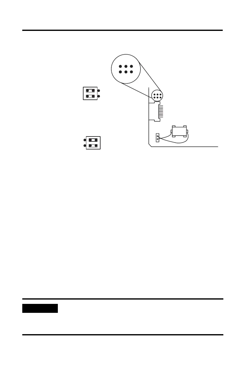
Figure 5 Jumper JW3 Pin Assignments and Settings
Module Jumper JW4
Use jumper JW4 to select one of the following configurations for the module ports.
• PRT1 Port = Program port with default communication settings
PRT2 Port = ASCII interface port
DH485 Port = Run time DH485 operation only
• PRT1 Port = ASCII interface port
PRT2 Port = ASCII interface port
DH485 Port = Program port with DH485 protocol
• PRT1 Port = Program port with programmed communication settings
PRT2 Port = ASCII interface port
DH485 Port = Run time DH485 operation only
• PRT1 Port = Program port with programmed communication settings
PRT2 Port = DF1 protocol
DH485 Port = Disabled
IMPORTANT
The first setting shown in Figure 6 is the default configuration.
When the jumper is set in this position, the module always
powers up in Command mode at 1200 bps, no parity, 8 data bits,
and 1 stop bit.
246
135
Pin
Assignments
1747-M4 UVPROM
(1)
(1)
This memory module is no longer available for sale from Rockwell Automation. Existing 1747-M3 and
1747-M4 memory modules are compatible with the 1746-BAS module and 1746-BAS-T module.
1747-M1 EEPROM
1747-M2 EEPROM
1747-M3 UVPROM
(1)
1771-DBMEM1 EEPROM
1771-DBMEM2 EEPROM
(Shipped Configuration)