508433-01Issue 2345Page 54 of 70
Proper Ground and Voltage
If a exible gas connector is required or allowed by
the authority that has jurisdiction, black iron pipe shall
be installed at the gas valve and extend outside the
furnace cabinet. The exible connector can then be
added between the black iron pipe and the gas supply
line.
CAUTION
A poorly grounded furnace can contribute to premature
ignitor failure. Use the following procedure to check for
ground and voltage to the integrated control.
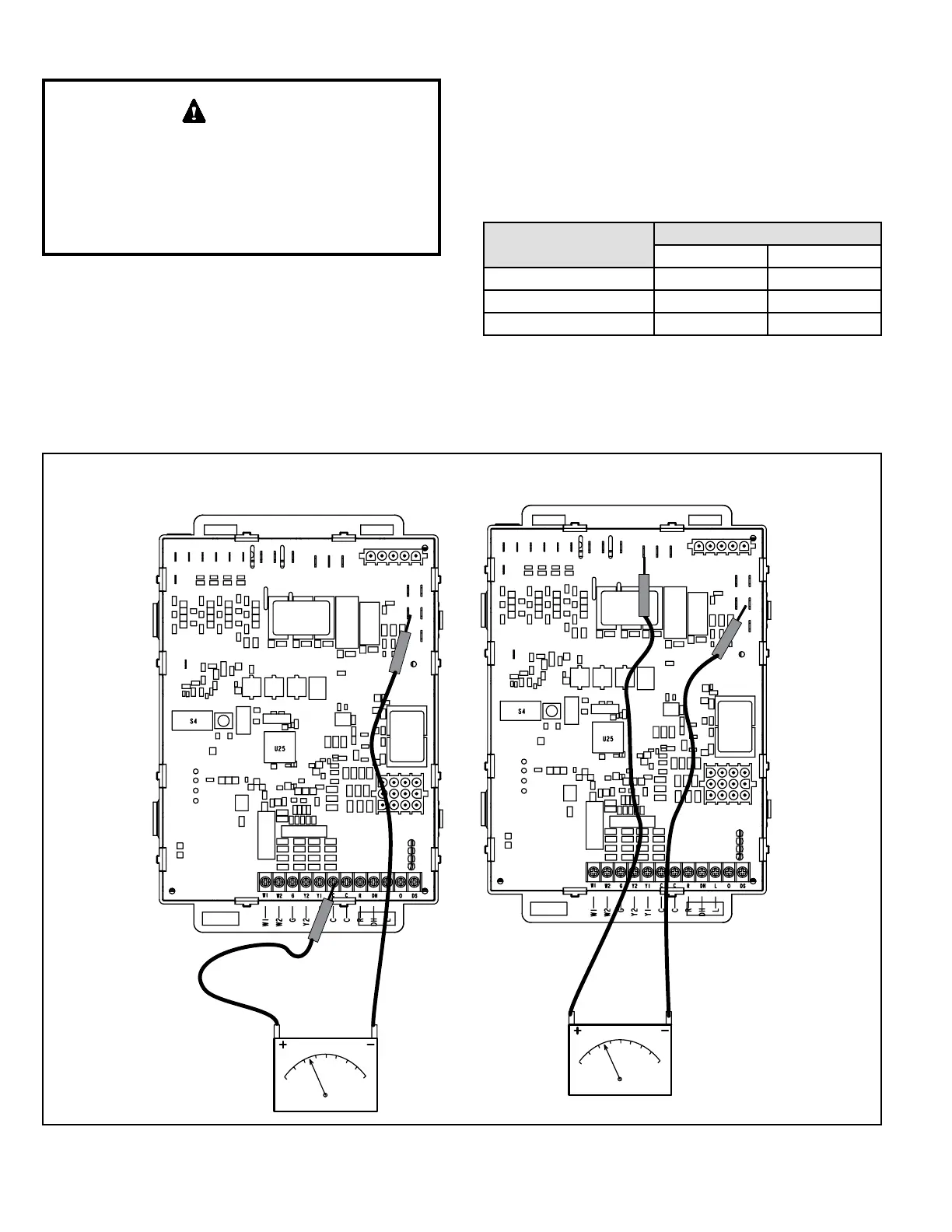
1. Measure the AC voltage between Line Neutral (spade
terminals) and “C” terminal (low voltage terminal
block) on the integrated control. See Figure 53. A wide
variation in the voltage between Line Neutral and “C”
as a function of load indicates a poor or partial ground.
Compare the readings to Table 20. If the readings
exceed the maximum shown in Table 20, make repairs
before operating the furnace.
2. In addition, measure the AC voltage from Line Hot
to Line Neutral (spade terminals) on the integrated
control. See Figure 53. This voltage should be in the
range of 97 to 132 VAC
Furnace Status
Measurement VAC
Expected Maximum
Power On Furnace Idle 0.3 2
CAI / Ignitor Enerigized 0.75 5
Indoor Blower Energized Less than 2 10
Table 20.
CHECK VOLTAGE BETWEEN LINE NEUTRAL
AND LOW VOLTAGE “C” TERMINAL
CHECK VOLTAGE BETWEEN LINE HOT
AND LINE NEUTRAL
Figure 53.