20
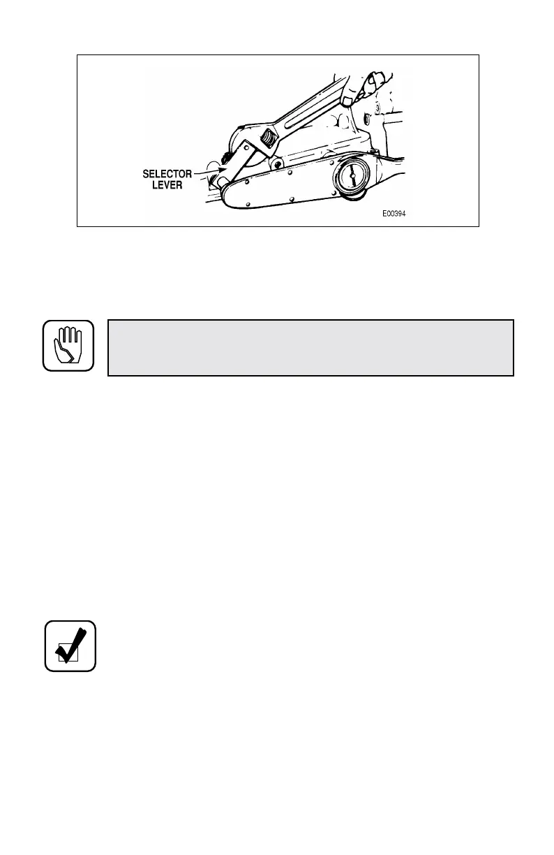
Figure 3–2. Tightening Selector Lever Nut
3–5. INSTALLING POWER TAKEOFF (PTO)
Space limitations will determine whether the PTO should be installed before or after
the transmission is installed.
• The prescribed backlash between the drive gear (in transmission) and driven
gear (in PTO) is 0.006–0.029 inch (0.15–0.73 mm) or as specified by the PTO
manufacturer.
• Determining PTO Backlash
— PTO not installed: backlash can be measured with special tool J 34814
(Figure 3–3). Reference SIL 50-TR-83 (latest revision).
— PTO installed: measure through the inspection port with a dial indicator
while rotating PTO shaft back and forth. Rattling gears indicate too much
backlash. Difficult engagement or whining gears indicate too tight a fit.
• Install the PTO unit and gasket(s) flush to the mounting pad; do not force.
Avoid bumping the snapring (Figure 3–4), which could be displaced. Secure
the PTO with six mounting bolts; tighten to 26–32 lb ft (35–43 N·m).
CAUTION: Cork or other soft gaskets must never be used to mount
the PTO. Use only shims or gaskets recommended by the PTO
manufacturer.
NOTE: One gasket (minimum) is required to prevent fluid leakage.
 Loading...


