21
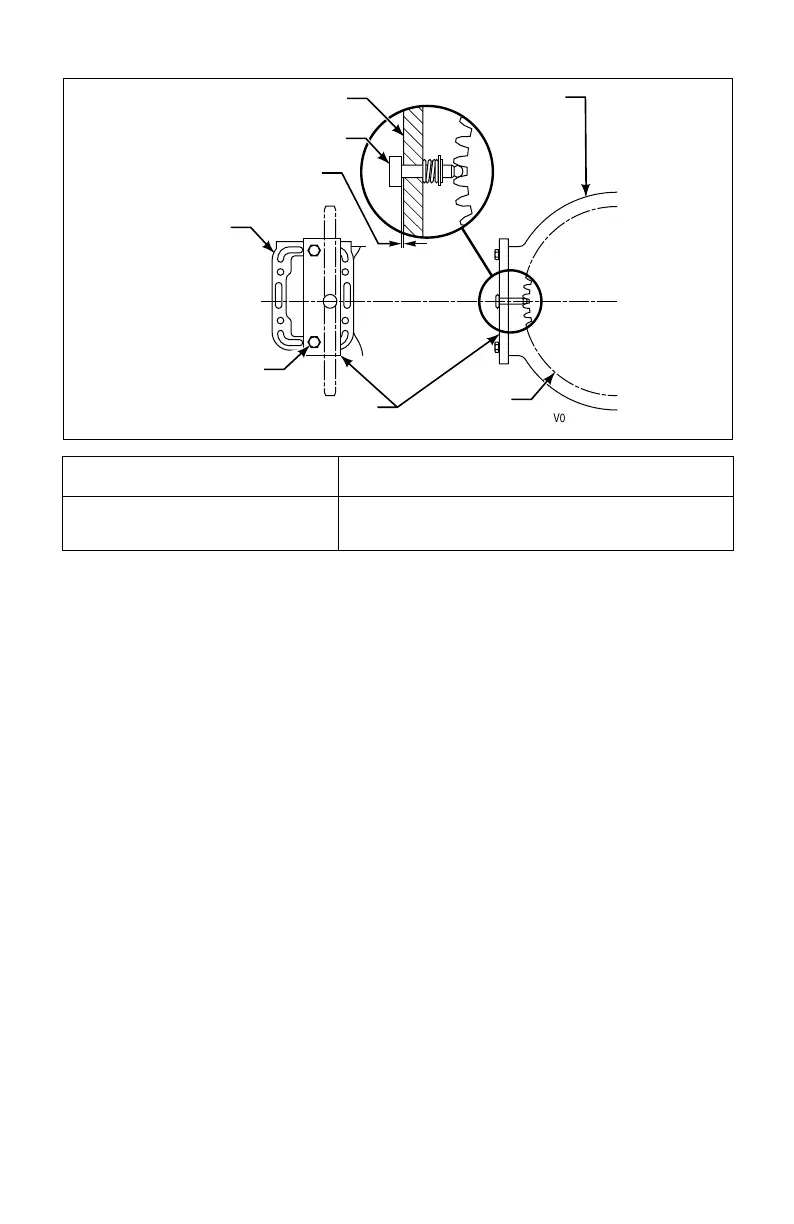
Figure 3–3. Measuring Turbine-Driven PTO Backlash
• On PTO assemblies that require pressure lubrication, install the lubrication
tube and fittings. The lubricating fluid comes from the line returning to the
transmission from the cooler. Fluid should be directed to the PTO lubrication
circuit after passing through a 0.032 inch (0.81 mm) restriction. (Usually, the
restriction is already located in the PTO.)
3–6. INSTALLING SHIFT MODULATION CONTROL
Install the modulation control after the transmission is put into the vehicle. Refer to
Paragraph 5–9.
Measurement Correction
0.011–0.045 in. (0.27–1.16 mm)
0.047–0.070 in. (1.19–1.78 mm)
one–0.030 in. Gasket (one 0.76 mm Gasket)
two–0.030 in. Gaskets (two 0.76 mm Gaskets)
V02394
TRANSMISSION
MAIN CASE
BASE PLATE
GAUGE PIN
PTO PAD
HOLD DOWN
BOLT
J 34814
PTO DRIVE
GEAR
MEASUREMENT
 Loading...


