32
5–6. CONNECTING COOLER, VACUUM LINES, AIR LINES
• Connect the lines from the transmission to the cooler forming a transmission
fluid-to-water counterflow in the cooler. Vertical-mounted coolers require the
transmission to-cooler line to be connected to the bottom port in the cooler to
avoid air-locking the cooler.
• Keep the lines away from exhaust pipes and components that cause chafing.
Avoid kinks and sharp bends. Tighten the cooler SAE No. 8 line fittings that
thread into the transmission housing to 15–22 lb ft (20–30 N·m).
• If a vacuum modulator is used, connect the vacuum modulator line at the
intake manifold.
• If an air modulator is used, connect the air modulator control line at the
control.
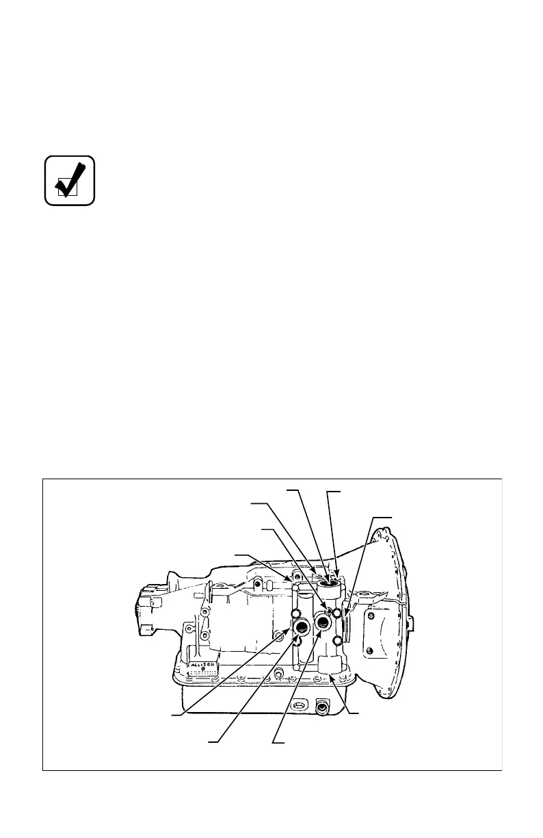
5–7. CONNECTING RETARDER CONTROLS
• Connect the wiring harness to the electrical connector on the retarder valve
body (Figure 5–3).
• Insert the temperature sending unit into the retarder valve body (Figure 5–3).
Tighten the sending unit connector to 15–20 lb ft (22–27 N·m).
Figure 5–3. AT 500R External Connections
NOTE: On retarder units there are two coolers to connect. See Figure
5–3 for proper location of cooler connections. Tighten cooler fittings
on the primary cooler to 40–50 lb ft (54–68 N·m). Tighten cooler
fittings on the secondary cooler to 15–22 lb ft (20–30 N·m).
RETARDER VALVE BODY
TRANSMISSION “FROM COOLER” PORT
FROM PRIMARY COOLER
TRANSMISSION
“TO COOLER” PORT
WIRING HARNESS
CONNECTOR
TO PRIMARY COOLER
TO SECONDARY COOLER
CONNECTS TO
TRANSMISSION “MAIN” PRESSURE TAP
(OPPOSITE SIDE OF TRANSMISSION)
CONNECTS TO TRANSMISSION
“TO COOLER” PORT
TEMPERATURE
SENDING UNIT
L02889.01

 Loading...


