30
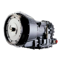
Figure 5–1. Pilot Tool for Installation (AT 500, AT 1500)
• Tighten the flexplate nuts (AT 543) to 34–40 lb ft (46–54 N·m).
• Tighten the drive cover bolts (all models except AT 543) to 42–50 lb ft
(57–68 N·m).
5–3. INSTALLING TRANSMISSION MOUNTING COMPONENTS
• Install all bolts, washers, cross-members, supports, and insulators required to
support the transmission in the vehicle frame.
CAUTION:
• For AT 540, AT 542 Series, AT 545 Series, and AT 1500 Series,
mounting pad bolts must penetrate the holes of the mounting
pads 1.24–1.39 inch (31.2–35.5 mm). Tighten mounting pad
bolts to 164–192 lb ft (222–260 N·m).
• For AT 543, mounting pad bolts must penetrate the holes of the
mounting pad 0.775–0.900 inch (19.69–22.86 mm). Tighten
mounting pad bolts to 164–192 lb ft (222–260 N·m).
V03008
PILOT PLATE
TAPER
FLYWHEEL
HOUSING
Screwdriver slot
to aid removal
Make from
M-10 x 38 mm
(1.5 in.) Bolt
 Loading...


