31
5–4. COUPLING TO DRIVELINE
• Couple the driveline companion flange or universal joint yoke to the
transmission output flange or yoke.
• Use the bolts, nuts, and torque specified by the vehicle manufacturer.
5–5. INSTALLING VACUUM OR AIR MODULATOR CONTROL
• Make sure the original sealring has been removed from the modulator can or
from the counterbore of the transmission housing.
• Install the sealring onto the modulator. Coat the sealring with oil soluble
grease.
• Install the modulator control into the transmission housing. Seat the sealring
in the counterbore in the housing.
• Install the modulator retainer so that the convex side of the curved ends are
toward the transmission. Secure the retainer with a
5
⁄16-18 x
3
⁄4 inch bolt.
Tighten the bolt to 10–16 lb ft (19–22 N·m).
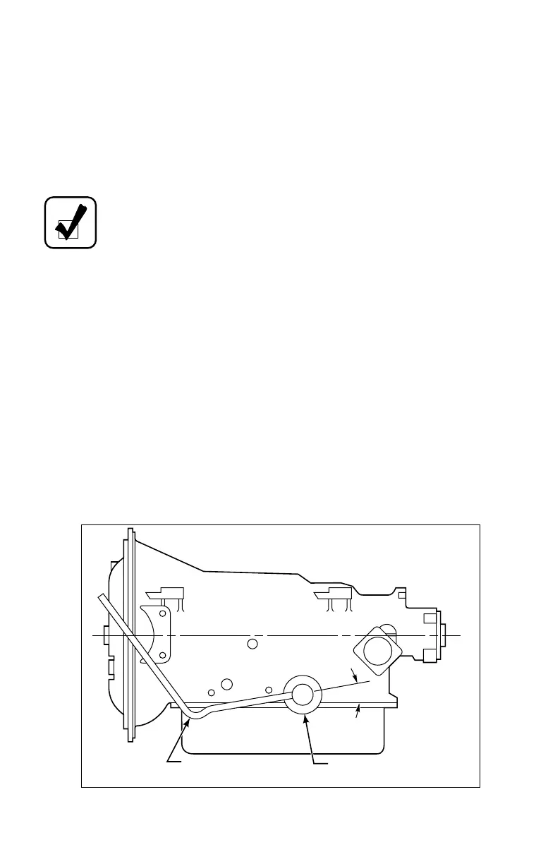
• Connect the vacuum or air line to the modulator. The tube connection at the
vacuum modulator should face toward the engine. The routing should be
approximately 10 degrees below horizontal and include a condensate trap
(goose neck) as shown in Figure 5–2.
Figure 5–2. Proper Relation of Vacuum Hose to Modulator Control
NOTE: There are 12V and 24V electric modulators available as of
June 1994. See SIL 27-TR-94.
CONDENSATE TRAP
VACUUM MODULATOR
10°
V03009

 Loading...


