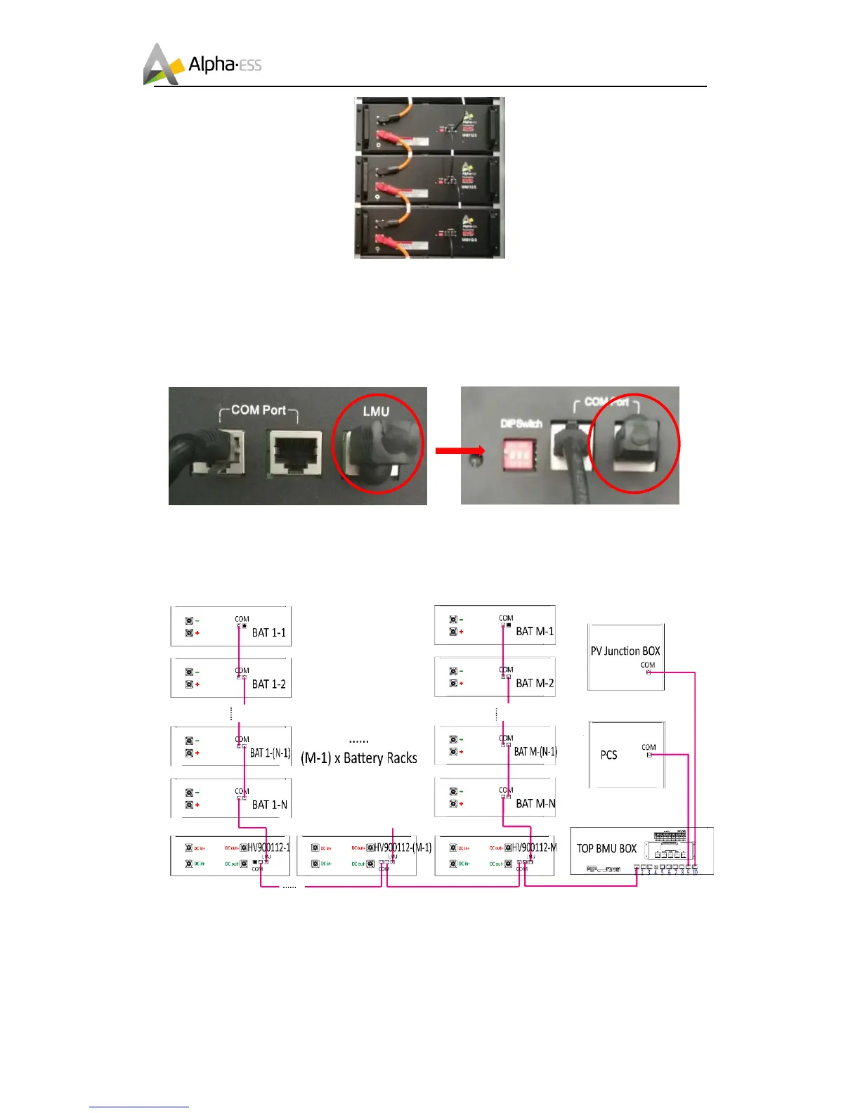
b. Take the item 8, the terminal resistance in Table 3 away from the LMU internet
access of HV900112 and insert it into the top battery COM port of one battery cluster. You
can see the detailed information in the battery picture.
c. Connect the comminucation cables to the LMU port of HV900112 control box as the
following diagram shows.
Figure 4-1 Battery side-communication cables connection