Assembly
Outdoor module L8 SPLIT/L12 SPLIT
Position L8 SPLIT/L12 SPLIT outdoors secured to a firm
surface, preferably a concrete foundation on a ground
stand near walls, or on a wall mounting.
It must be positioned so that the lower edge of the evap-
orator is at the level of the average local snow depth,
however a minimum of 200 mm. L8 SPLIT/L12 SPLIT should
not be positioned next to noise-sensitive walls, for ex-
ample, next to a bedroom. Also ensure that the location
does not inconvenience the neighbours. Care must be ex-
ercised so that the heat pump is not scratched during in-
stallation.
Large amounts of condensation water as well as melt
water from defrosting can be produced. Provide good
drainage at the installation area and make sure water
cannot run out onto paths or the like during periods that
ice can form.
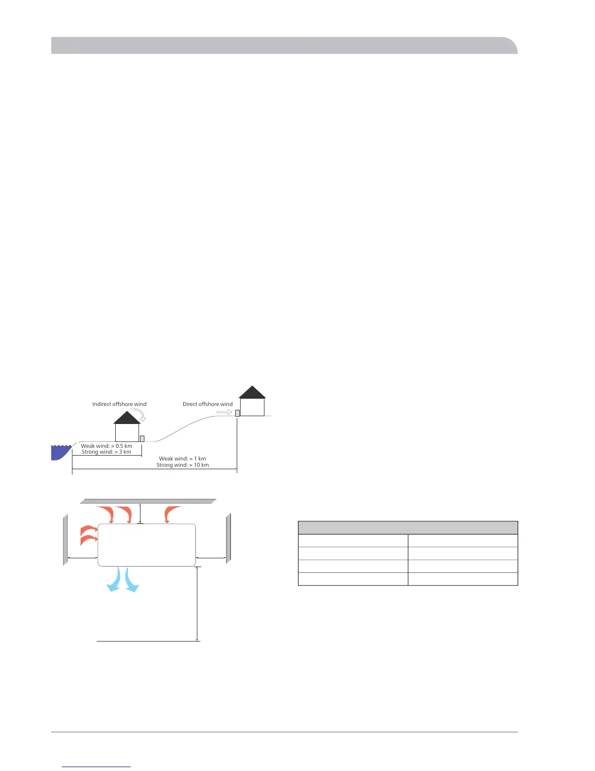
The distance between L8 SPLIT/L12 SPLIT and the house
wall must be at least 150 mm. Ensure that there is at least
one metre of free space above L8 SPLIT/L12 SPLIT. L8
SPLIT/L12 SPLIT must not be placed so that recircula-
tion of the outdoor air is possible. L8 SPLIT/L12 SPLIT
must not be placed in a windy location where it is ex-
posed to direct strong winds. This reduces output and
impairs efficiency and also has a negative effect on the
defrosting function.
For wall installation, ensure that vibrations do not affect
the inside of the house. Also ensure that the wall and
mounting can take the weight of the heat pump.
■
It is recommended that HM 8-12 SPLIT is installed in a
room with existing floor drainage, most suitably in a
utility room or boiler room.
■
Route pipes so they are not fixed to an internal wall that
backs on to a bedroom or living room.
■
Ensure that there is approx. 500 mm free space in front
of and 220 mm above the product for any future service.
EHZK 90 SPLIT
■
It is recommended that tank EHZK 90 SPLIT is installed
in a room with existing floor drainage, most suitably in
a utility room or boiler room.
■
Hang the tank with its back to an outside wall, ideally
in a room where noise does not matter. If this is not
possible, avoid placing it against a wall behind a bed-
room or other room where noise may be a problem.
■
Secure the wall bracket (enclosed) to a wall of a suitable
material. Hook the tank onto the wall bracket. Install the
enclosed screw in the upper hole on the wall bracket to
hold the tank in place.
■
Route pipes so they are not fixed to an internal wall that
backs on to a bedroom or living room.
■
Ensure that there is approx. 500 mm free space in front
of, 600 mm to the right and 220 mm above the product
for pipework and any future service. Ensure that there
is sufficient space for the drain valve under the tank.
■
EHZK 90 SPLIT is provided with a manometer, a drainage
valve and a safety valve. The safety valve (FL2) should be
installed as close to the tank as possible. The drainage
valve should be positioned at the lowest point. The loc-
ation of the manometer (BP5) is less sensitive.
WWS 300 SPLIT, WWS 500 SPLIT
■
It is recommended that the water heater is installed in
a room with existing floor drainage, most suitably in a
utility room or boiler room.
■
The surface must be firm, preferably a concrete floor or
foundation.
■
The unit can be aligned using the adjustable feet.
■
Route pipes so they are not fixed to an internal wall that
backs on to a bedroom or living room.
■
Ensure that there is approx. 500 mm free space in front
of and 220 mm above the water heater for any future
service.
Dimensioning expansion vessel
HM 8-12 SPLIT is equipped with a membrane expansion
vessel on 18 I. A larger expansion vessel may be required
depending on installation. The expansion vessel must be
dimensioned for every installation. If a larger expansion
vessel is required, the existing expansion vessel can be shut
off.
Volume per component
4 lHM 8-12 SPLIT
30 lEHZK 90 SPLIT
300 lWWS 300 SPLIT
500 lWWS 500 SPLIT
SPLIT20
For the Installer
General information for the installer