Setting max power, electrical addition
Setting the different maximum immersion heater outputs
is performed using the knob (R25) on the load monitor
board (AA22). Set value displayed in menu 8.3.2. The fol-
lowing table only applies when menu 9.2.8 Add. heat type
is set to "Internal power 1" (factory setting).
L3 (A)
Compressor
L2 (A)L1 (A)Max.
electric
power
Knob
posi-
tion
Immer-
sion
heater,
output
(kW)
offon
015000-0.0
0154.35.31-2.0
0158.79.72A4.0
01513143B6.0
13-13144C9.0
Setting max boiler temperature
The setting of the different maximum boiler temperatures
is made on the knob (R26) on the load monitor board
(AA22). Set value is displayed in menu 9.3.1.
Knob positionBoiler temperature
A55
B60
C65
D65
E65
F65
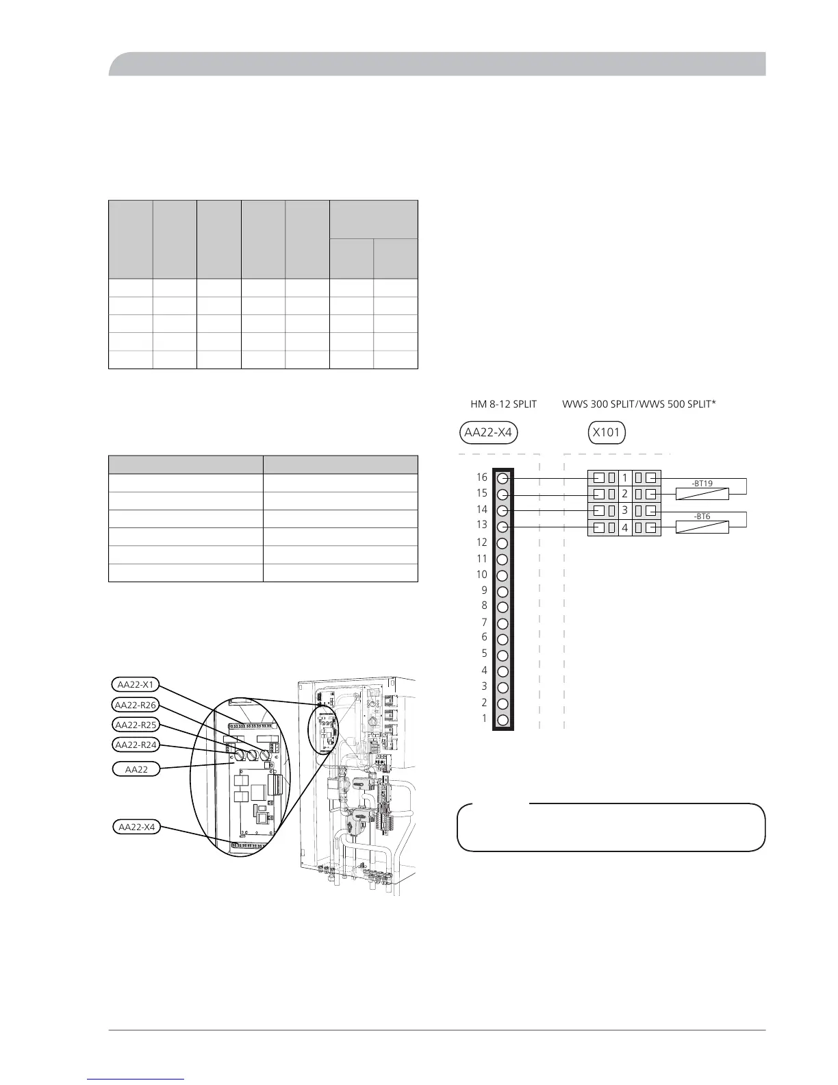
EBV board, terminal and wiring diagram
The following connections are made on the EBV board
(AA22).
See page 70 for complete wiring diagram of board.
AA22-R26
AA22-R25
AA22-R24
AA22
AA22-X4
AA22-X1
Connecting the outside sensor
Install the outdoor temperature sensor (BT1) in the shade
on a wall facing north or north-west, so it is unaffected by
the morning sun for example. Connect the sensor to ter-
minal block X1:1 and X1:2 on the load monitor board
(AA22) via cable grommet UB4. Use a 2 core cable of at
least 0.5 mm
2
.
If the outside sensor cable runs close to power cables,
shielded cable must be used.
If a conduit is used it must be sealed to prevent condensa-
tion in the sensor capsule.
Connecting the temperature sensor hot water
charging
The water sensor (BT6) and immersion heater sensor (BT19)
are located on EHZK 90 SPLIT/WWS 300 SPLIT/WWS 500
SPLIT and are connected using a cable between HM 8-12
SPLIT (terminal block AA22-X4) and E (terminal block
X101). Use a 4-core cable of at least 0.5 mm2 cable area.
1
2
3
4
5
6
7
8
AA22-X4
9
10
11
12
13
14
15
16
X101
4
2
3
1
-BT19
-BT6
WWS 300 SPLIT/WWS 500 SPLIT*HM 8-12 SPLIT
*The hot water sensor (BT6) is not used in EHZK 90 SPLIT.
Connecting the current limiter
NOTE
Only applies to 3X400V.
When many power consumers are connected in the
property at the same time as the electric addition is oper-
ating, there is a risk of the property's main fuse tripping.
HM 8-12 SPLIT is equipped with an integrated current
limiter that controls the electrical steps and the com-
pressor. If necessary, the electrical steps are disengaged
and/or the compressor frequency is reduced.
A current sensor should be installed on each incoming
phase conductor in to the distribution box to measure the
current. The distribution box is an appropriate installation
point.
37SPLIT
For the Installer
Electrical installation