Pipe dimensions and materials
Liquid pipeGas pipe
Ø9.52 mm (3/8")Ø15.88 mm (5/8")Pipe dimension
Flare - (3/8")Flare - (5/8")Connection
Copper quality SS-EN 12735-1 or
C1220T, JIS H3300
Material
0.8 mm1.0 mmMinimum material
thickness
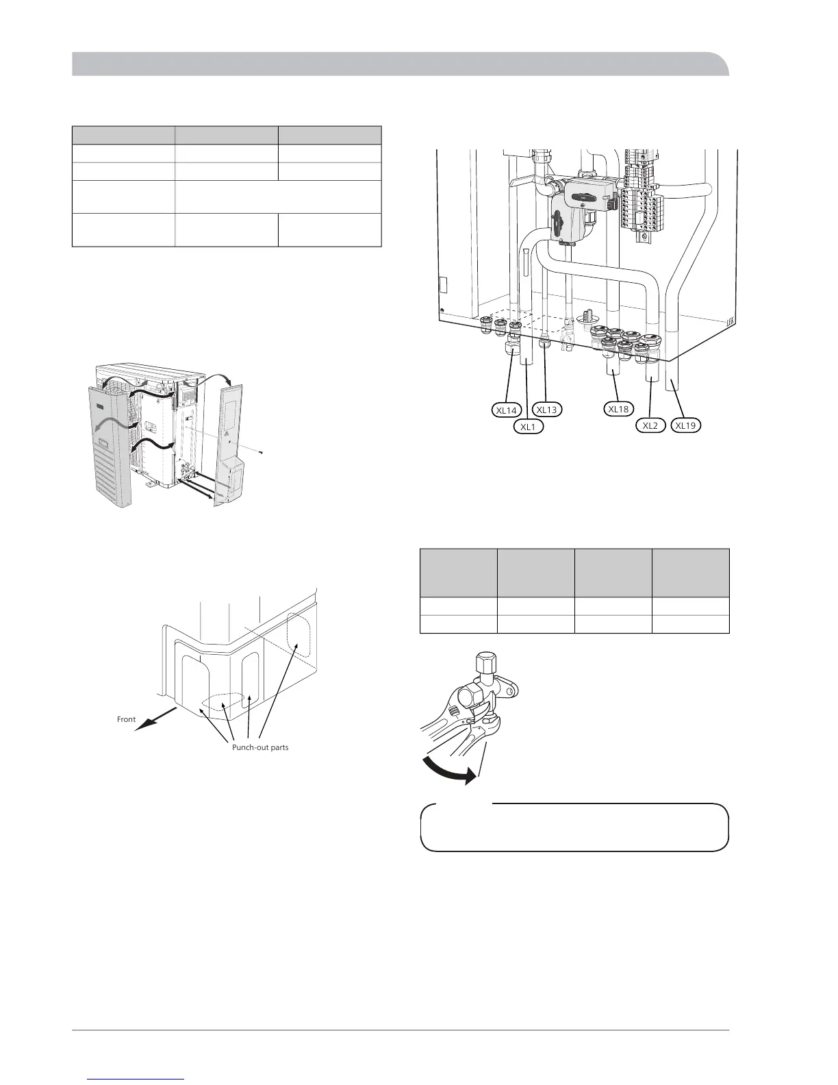
Pipe connection
■
Perform pipe installation with the service valves (QM35,
QM36) closed.
■
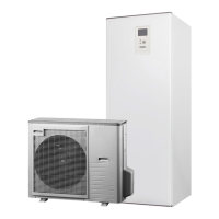
L8 SPLIT
Remove the side panel on L8 SPLIT/L12 SPLIT during in-
stallation to facilitate access.
L12 SPLIT
Remove a "punch-out" part from the outer panel on L8
SPLIT/L12 SPLIT, where the pipes are to be routed. The
image below, shows possible pipe outlets.
HM 8-12 SPLIT
The image below, shows possible pipe outlets.
■
Ensure that water or dirt does not enter the pipes.
■
Bend the pipes with as large a radius as possible (at least
R100~R150). Do not bend a pipe repeatedly. Use a
bending tool.
■
Connect the flare connector and tighten to the following
torque. Use the "Tightening angle" if a torque wrench
is not available.
Recommen-
ded tool
length (mm)
Tightening
angle (°)
Tightening
torque (Nm)
Outer diamet-
er, copper
pipe (mm)
20030~4534~42Ø9.52
30015~2068~82Ø15.88
NOTE
Gas shielding must be used when soldering.
SPLIT26
For the Installer
Pipe installation