11Subject to technical amendments without prior notice | 83055800gUK – Translation of the original operating manual | ait-deutschland GmbH
7 Electrical installation
7.1 Establishing the electrical
connections
IMPORTANT
Irreparable damage to the compressor due to wrong
rotatingeld!
► Ensureaclockwiserotatingeldforthecompres-
sor’sloadsupply(for400Vconnectiononly).
Basic information relating to the electrical
connection
● Any specications by the local energy supply
company apply to electrical connections
● Equip the power supply for the heat pump with
an all-pole miniature circuit-breaker with at least
3mmcontactspacing(IEC60947-2)
● Note the tripping current level ( “Technical
data / scope of supply”, page 16)
● Comply with the electromagnetic compatibility
regulations(EMCregulations)
● Comply with current EMC requirements for house-
hold appliances
● Install unshielded power supply cables and
shieldedcables(buscables)sucientlyfarapart
(>100mm)
● Maximum line length: 30m.
Permissible type of bus cable:
3 x 0,5 mm², Standard shielded ÖLFLEX
Pull in the cables and conductors and create
the connections
1. Route the pre-assembled 8 m cable for the heat
pump inside the building to the hydraulic unit.
2. Connect the compressor load cable to the hydrau-
lic unit using the 5-pin plug included in the heat
pump scope of delivery, “load connection to L1”.
See “Terminal diagram/circuit diagram for hydrau-
lic unit”
3. Route the bus cable in a cable conduit up to the
building feed-through and from there on to the hy-
draulic unit.
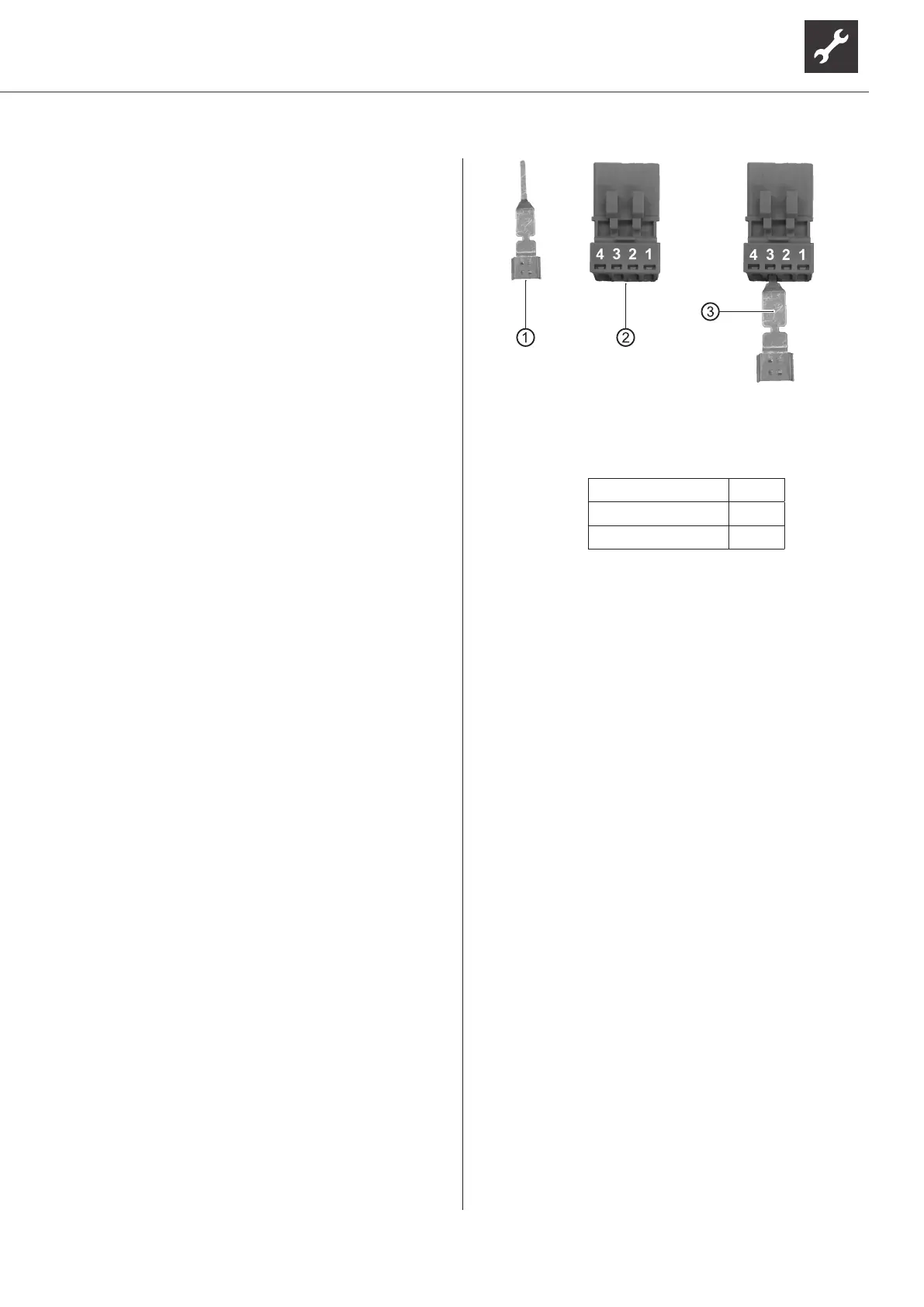
4. Connect the bus cable (communication) to the bus
plug included in the heat pump scope of delivery:
Connect the shielding of the bus cable to the con-
tact spring supplied with the plug and install the
contact spring in Pin 3 of the bus plug.
1 Contact spring
2 Bus plug
3 ContactspringinstalledinBusplug(Pin3)
Further bus plug assignment:
Bus cable wire 1 Pin 1
Bus cable wire 2 Pin 2
Bus cable wire 3 Pin 4
5. Connect the bus plug to the hydraulic unit.
6. Connect the control voltage to the hydraulic unit
using the plug included in the heat pump scope of
delivery.
“Terminal diagram/circuit diagram for hydraulic unit”

 Loading...