9Subject to technical amendments without prior notice | 83055800gUK – Translation of the original operating manual | ait-deutschland GmbH
Installation site requirements
● Only install outdoors
Clearance dimensions were complied.
“Minimum clearances”, page 28
Free air intake and blowing air are possible with-
out any air short-circuit.
The surface is suitable for installation of the unit:
● The foundation is level and horizontal
● The surface and the foundation have a lo-
ad-bearing capacity sucient for the unit’s
weight
Ground surface in the air outlet area of the heat
pump is permeable to water
5.5 Installation with a wall bracket
“Wall bracket installation instruction”
“Wall duct installation instruction”
“Installation plans/minimum clearances/
drill template”
The wall bracket is only suitable for solid, load-bearing
walls. In a timber-frame construction with facing, the
oorbracketshouldbeusedduetothepossibletrans-
fer of structurally borne sound to the interior.
5.6 Installationonaoorbracket
The device can be installed near a wall or as a free
eld installation.Ideally, theheatpumpshould bein-
stalled where it is protected from wind. If this is not
possible, we recommend installing it at right angles
to the prevailing direction of wind or air ducting in the
main wind direction.
Placethedeviceonaload-bearing,rmandhorizon-
tal foundation. The foundation must not be connect-
ed to the building Make sure that the foundation is de-
signed for the weight of the heat pump.
“Floor bracket installation instruction”
“Wall duct installation instruction”
“Installation plans/minimum clearances/
view of foundation”
NOTE
When installing with a wall duct, make sure
the wall clearance is correct.
6 Installation of hydraulic
system
6.1 Condensate drain
The condensate precipitated from the air must be re-
moved frost-free via a plastic condensate pipe with
a minimum diameter of 40 mm. If surfaces are wa-
terpermeable,itissucientforthecondensatedrain
pipe to be routed vertically into the ground to a depth
of at least 90 cm.
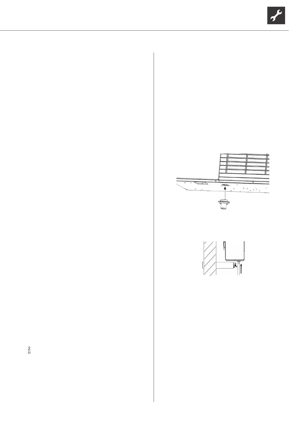
Install the condensate pipe nozzle on the condensate
drain, which is included in the scope of delivery for the
device, on the underside of the device using the en-
closed screws:
Outdoors
Connectthecondensate pipe(wallductaccesso-
ry) to the condensate pipe nozzle.
“Wall duct installation instruction”
The condensate pipe must not be inserted into the
groundonitsown,itmustrstbeinsertedintoasec-
ond pipe that is suitable for installation in the ground
(suchasawastewaterpipe).
The connection between the pipes must be sealed. It
must be possible to compensate the length. The pipe
on the device must not press against the ground, it must
be possible to slide it.
Sucientseepageofthedrainingcondensateintothe
ground must be ensured.
“External condensate line connection“, page 29

 Loading...