Iftheconnectionleaks:
1. Undoconnectionandcheckpipefordamage.
2. Tighten the union nut hand-tight and retighten with
the open-ended spanner with 1/8 to 1/4 turn, as
the clamping ring is already in a clamping position.
Connect the unit to the heat source,
domestic water pipes and heating circuit
1. Install shut-off devices in the heating circuit.
2. Insert the vent at the highest point of the heat
source and the heating circuit.
3. Recommendation: Fit a dirt lter with mesh size
0.9 mm onto the heat source inlet.
4. Connectthedomestichotwatertankaccordingto
the local regulations.
5. Recommendation: To balance out pressure
uctuations and water hammers and avoid
unnecessary loss of water, install an expansion
vesselwiththrough-owtting.
6. Ensure that the operating overpressures
( “Technical data/Scope of supply” on page
24) are not exceeded. Install pressure reducer
if necessary.
6.4 Connect the electrical cables
ATTENTION
Irreparable damage to the compressor due to wrong
rotatingeld!
► Ensurethat there is aclockwise rotating eld for
the compressor load infeed.
Basic information on the electrical connection
NOTE
Ensure that the unit is supplied with electricity
atalltimes.Afterworkinginsidetheunitand
attaching the unit panelling, switch the power
supplybackonimmediately.
● The specications of the local power supply
company may apply to electrical connections.
● Fit the power supply for the heat pump with an all-
pole miniature circuit-breaker with at least 3 mm
contact spacing (IEC 60947-2).
● Note the level of the tripping current
( “Technical data/Scope of supply” on page
24).
● Comply with the electromagnetic compatibility
regulations (EMC regulations).
–
Lay the control/sensor cables and unit supply
cablesufcientlyfarapart(>100mm).
–
Lay unshielded power supply cables and
shieldedcables(LINbuscable)withsufcient
distance between them.
● Do not lengthen the patch cable and LIN bus
cable. LIN bus cables up to 30 m long can be
used.
Pullinthecablesandconductorsandmake
the connections
1. Strip the sheathing of electrical cables before
laying in the cable duct of the control box.
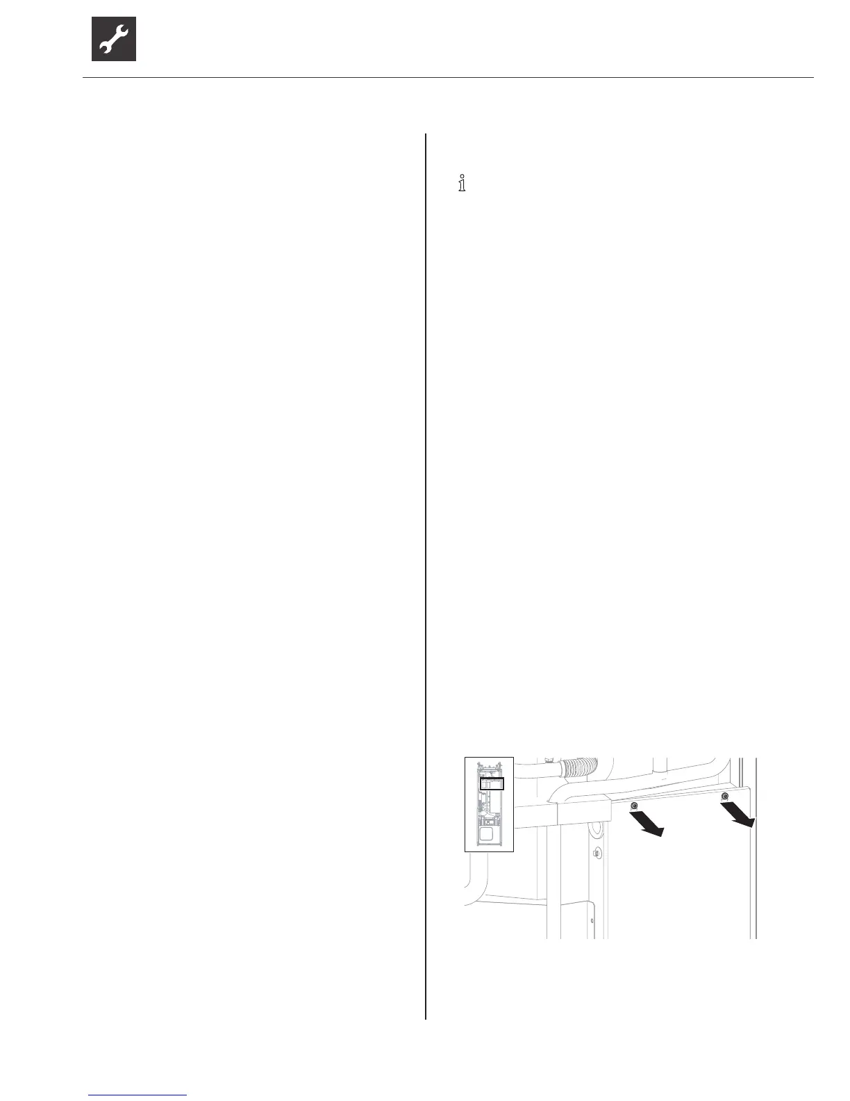
2. Open electrical switchbox:
–
Undo 2 screws at the top of the cover panel of
the electrical control box.
–
Unhookcoverpanel.
 Loading...