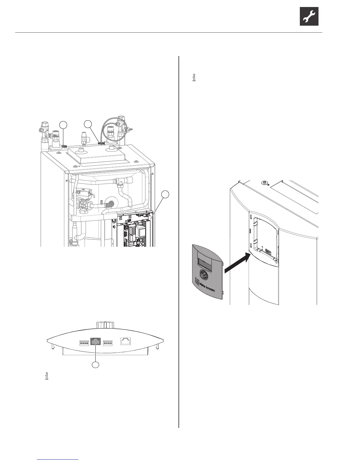
3. Lay the control / sensor cables and unit supply
cable and connect:
–
Route cables through the reserve conduits (1)
and (2) only, from above into the inside of the
unit.
–
Route cables from underneath through the
cable openings in the control box (3).
2
1
3
–
Connect cables to the respective terminals
( “Terminal diagram” on page 43).
Control the controller via a PC
1. During installation lay a shielded network cable
(category 6) through the unit.
2. Plug the RJ-45 connector of the network cable
into the bush of the control unit (1).
NOTE
The network cable can be retrotted at any
time.Todothis,dismantlethemaskingplate.
6.5 Installing the control unit
NOTE
The control unit can be inserted in a recess in
the front panel of the unit or can be installed
on the wall.
Insert the control unit in the unit and connect
1. If required: Remove masking plate from the
slot provided. To do this, press the latching lugs
together and push out of the openings.
2. Removelmfromtheplasticelementofthefront
panel.
3. Position the control unit in the recess in the front
panel of the unit and press the latching lugs into
the openings.
4. Cut the cable to length generously so that the
front panel can be removed and placed to the side
of the unit. Do not cut the cable ties for strain relief
of the LIN bus cable at the electric control box.
–
LINbuscableapprox.1.1mfromthexingof
the strain relief at the electrical control box
–
All other cables approx. 1.2 m
5. UsecabletiestoxtheLINbuscabletoawebof
the cover around 20 cm in front of the connector
(strain relief).
6. Push the cable through the opening in the front
panel of the unit from below and into the control
unit.
7. Insert cover in the free slot.
 Loading...