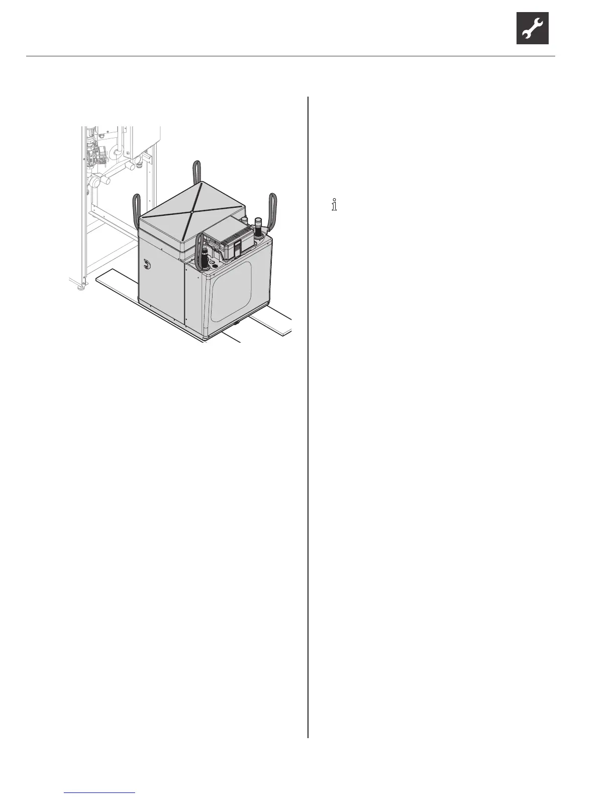
15. Pull out the module box completely and place it on
the boards.
6.2 Installing the module box
1. Place the module box carefully in the bottom in the
heating station and slowly and carefully push it in.
–
At the same time, lift and hold the nut on the
heatingow.
–
Ensure that none of the pipes are damaged.
2. Attach the two side retaining screws.
3. Connect the heating ow and hydraulic
connections. At the same time, replace O-rings
on the heat pump connections (separatepack
included).
4. Perform pressure test and insulate pipes with the
enclosed insulation hoses (separatepack).
5. Connect the electrical connections.
–
Plug in 2 white connectors at the bottom of
the electrical control cabinet. Ensure that the
connectors move easily and the lugs latch into
position.
–
Plugintheblackrectangularconnectoratthe
top of the module box.
6.3 Install the hydraulic connections
ATTENTION
Damage to the copper pipes due to unacceptable
loading!
► Secure all connections against twisting.
NOTE
The heat source can be connected from the
top, right or left.
The heat source system has been installed in
accordance with the specications ( planning
& design manual, dimensioned diagrams,
installation plans).
Cross-sections and lengths of the pipes for the
heating circuit and heat source are dimensioned
adequately.
The free pressure of the circulation pumps
produces at least the minimum throughput
required for the unit type ( “Technical data/
Scope of supply” on page 24).
The cables for the heat source and the heating
arexedtothewallorceilingviaaxedpoint.
Installthecompressionttingsandball
valves
ATTENTION
Leaks or fracture of the union nut due to excessive
force!
► Tighten the union nut only as far as described
here.
1. Check pipe ends for scratches, dirt and
deformation.
2. Checkproperpositionoftheclampingringonthe
tting.
3. Push the pipe through the clamping ring up to the
limitstopinthetting.
4. Tighten the union nut hand-tight and attach
waterproofmarking.
5. Tighten union nut with 3/4 rotation.
6. Checkconnectionforleaks.
 Loading...