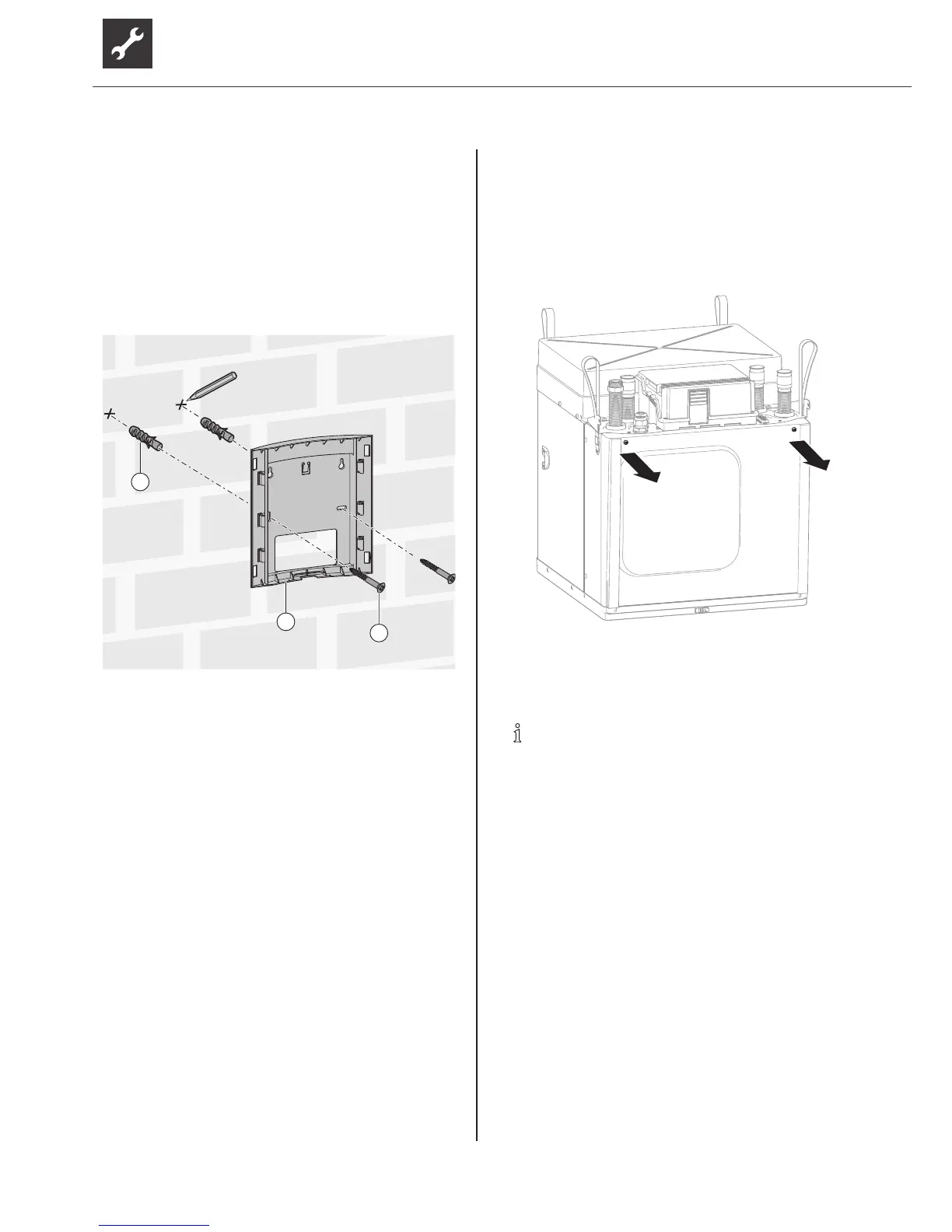
Mount the control unit on the wall and
connect
1. Releasetherearbracketfromthecontrolunit.
2. Cut off latching lugs (if visually obtrusive).
3. Mark 2 drillholes ( “Dimensioned drawing of
controlunit,wall-mountedbracket”onpage34).
4. Fix the wall-mounted bracket (2) with
2 wallplugs (1) and 2 screws (3).
1
2
3
1.
2.
3.
4.
5. Feed in the cables from the wall (e.g. in-wall box)
or from below.
6. Push the control unit onto the wall-mounted
bracket.
7. Route the LIN bus cable from the top right-hand
side at the rear from the heat pump and plug into
the control unit at the bottom.
8. Push on cover. If applicable, position second
cover (accessories) on the second unused slot.
7 Flushing,llingandventing
7.1 Remove the front panel of the
module box
► Unscrew the front panel of the module box.
7.2 Heating water quality
NOTE
● For detailed information refer, among
other things, to the VDI Guidelines
2035 “Vermeidung von Schäden in
Warmwasserheizanlagen” (preventing
damage in hot water heating systems).
● Required pH value: 8.2 ... 10
● for aluminium materials: pH value:
8.2 ... 8.5
► Fill the system with deionised heating water (VE
water) only or VDI 2035 (low-salt operation of the
system).
 Loading...