Modbus Integrator's Guide for the CXC HP | 2 - Using Modbus
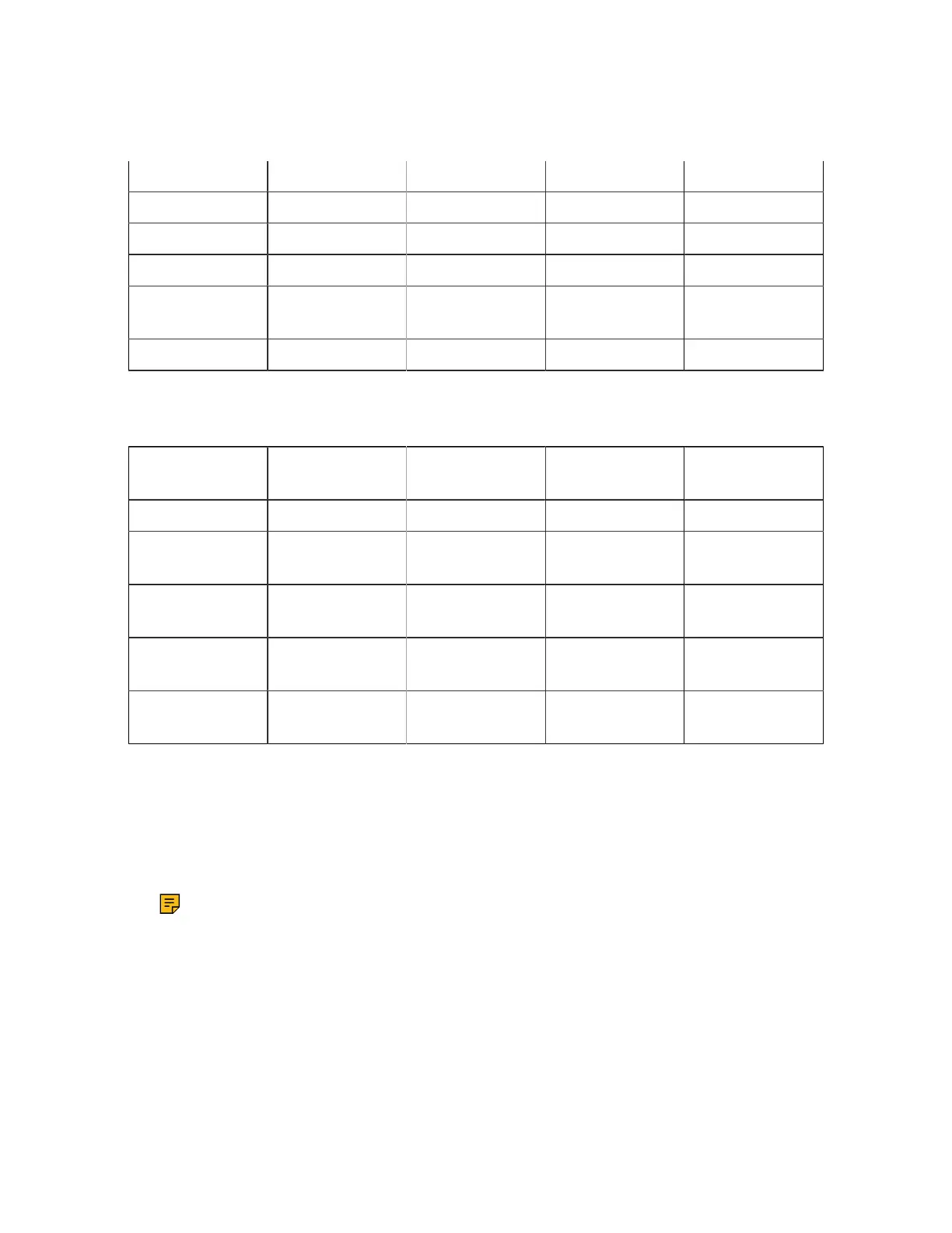
Table 3. Modbus Address Allocation for DC System Data (continued)
DC System: Battery 1 5157 15157 35157
DC System: Loads 120 5183 15183 35183
DC system: Shunt 120 6385 16385 36385
DC system: CT 120 6627 16627 36627
DC system: Discon-
nect
10 6869 16869 36869
DC system: Rectifier 256 6991 16991 36991
Table 4. Modbus Address Allocation for AMPS HP System Data
Source Maximum Number
of Source Items
Start of Coil Status
Register (01)
Start of Input Status
Register (02)
Start of Values Reg-
ister (04)
AMPS HP System 1 5001 15001 35001
AMPS HP System :
Breakers/Fuses
10 6503 16503 36503
AMPS HP System :
Bypass Switch
5 6625 16625 36625
AMPS HP System :
T2S
4 6707 16707 36707
AMPS HP System :
Inverters
32 6773 16773 36773
This table shows:
• Source item that has Modbus data available,
• Maximum number of items that can be viewed over Modbus in each register,
• Starting address for each type of data.
Note:
Modbus client software sometimes requires addresses to be entered in the range 1 - 9999. If this
is the case, drop the leftmost digit for addresses that are greater than 9999. The Modbus client
software will then use the combination of register and address to formulate the correct address for
the query.
Not all register addresses will be populated with data. For example, the controller does not actually have
any coils (relays). A request for coil data at address 1 will return zero.
Page 12 0350114-J0 Rev G
 Loading...