Chapter 5 Parameter Introductions
http://www.acdrive-china.com
115
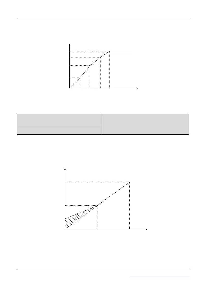
If P0.12 is set to 4, you can define V/F curve by P0.13~P0.18, as shown in Fig. 5-0-3.
The V/F curve can be defined with 4 points to meet special load characteristics demand.
Vol tage %
Frequency (Hz)
P0.14
P0.16
Basic Frequency
(P0.06)
P0.18
100%
P0.13 P0.15 P0.17
Fig. 5-0-3 V/F-curve defined by user
P0.19 Torque boost mode
Range: 0.0~3 0.0%
【S2R4GB~3004GB:40%;
35R5GB/37R5PBand below:0.0%】
Note:
In order to compensate the torque dropping at low frequency, the ac drive can boost the
voltage to boost the torque. If P0.19 is set to 0, magnetic flux vector modulation is
enabled and if P0.19 is set to non-zero, manual torque boost is enabled, as shown in Fig.
5-0-4.
Output voltage
Output Freq.
Basic operation frequencyCut-off Freq. for torque boost
Manual
torque boost
Max output
voltage
Fig. 5-0-4 Manual torque boost diagram
(shadow area is the boost value)
Tips:
1. Wrong parameter setting can cause overheat or over-current protection of the motor.
2. When the ac drive drives synchronous motor, torque boost function is recommended