Chapter 5 Parameter Introductions
http://www.acdrive-china.com
142
P3.15 Terminal Y2 function definition
Range: 0~30【2】
P3.16 Output function of Relay 1 (TA/TB/TC)
Range: 0~30【19】
P3.17 Output function of Relay 2
(BRA/BRB/BRC)
Range: 0~30【0】
Note:
For model 3004GB and the belows, function code P3.14, P3.15 are reserved and cannot
been modified. At the same time, output function No. 26 and 27 are reserved , there is
no output; Function code P3.17 is used for “the terminal output hold time setting of
fixed-length arriving”. The details are below:
◆This series ac drive has 5 digital outputs. The multi-function output terminals, D0, Y1,
Y2, Relay 1, and Relay 2 are programmable. They can be selected to output some
controlling and monitoring signal according to the application requirement. Refer to
Table 5-3-5.
◆If collectors are selected as PLC running steps output or fault output, D0, Y1, Y2 must
be selected as the same function (26, or 27) to make the combination effective.
◆Fault type and running steps refer to Table 5-3-4.
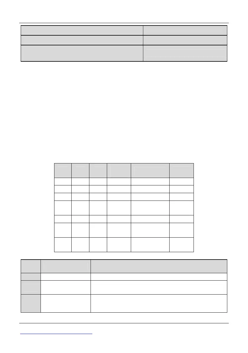
Table 5-3-4 Fault Type and Running Step
Y2 Y1 D0
Fault
Type
Meaning Steps
OFF OFF ON OC Over-Current T1
OFF ON OFF SC Short Circuit T2
OFF ON ON OU Over Voltage T3
ON OFF OFF Uu1
Under
Voltage
T4
ON OFF ON OH1 Overheat T5
ON ON OFF OL2
Ac drive
Overload
T6
ON ON ON EH
External
Fails
T7
Table 5-3-5 Multi-function Output
Setting Function Description
0 NULL None
1 RUN
The ac drive is in running state, the output of terminal is
valid.
2
FAR Frequency
arriving
Refer to description of parameters P3.18 (Frequency
arriving signal (FAR)).