Chapter 2 Installation and Wiring
http://www.acdrive-china.com
40
Power Supply
3-phase
380V
50/60Hz
MC
DCL DC reactor
(connect externally,optional
parts for 3132GB/3160PB or below)
Braking resistor
or braking unit
Motor
Analog output
4~20mA current
2~10V voltage
Open collector pulse
output terminal 0~50Khz
Multi-function input 1
Bi-direction open
collector output
Output1
Ground
Programmable
relay output
Common terminal
RS485 communication
interface
keyboard
Frequency Reference
Frequence preset
potentiometer
(Input resistance
>500 kΩ)
High speed pulse input
Ground
Max input
frequency:
50 KHz
Output2
Multi-function input 2
Multi-function input 3
Multi-function input 4
Multi-function input 5
Multi-function input 6
Multi-function input 7
Multi-function input 8
Programmable
relay output
Frequency meter
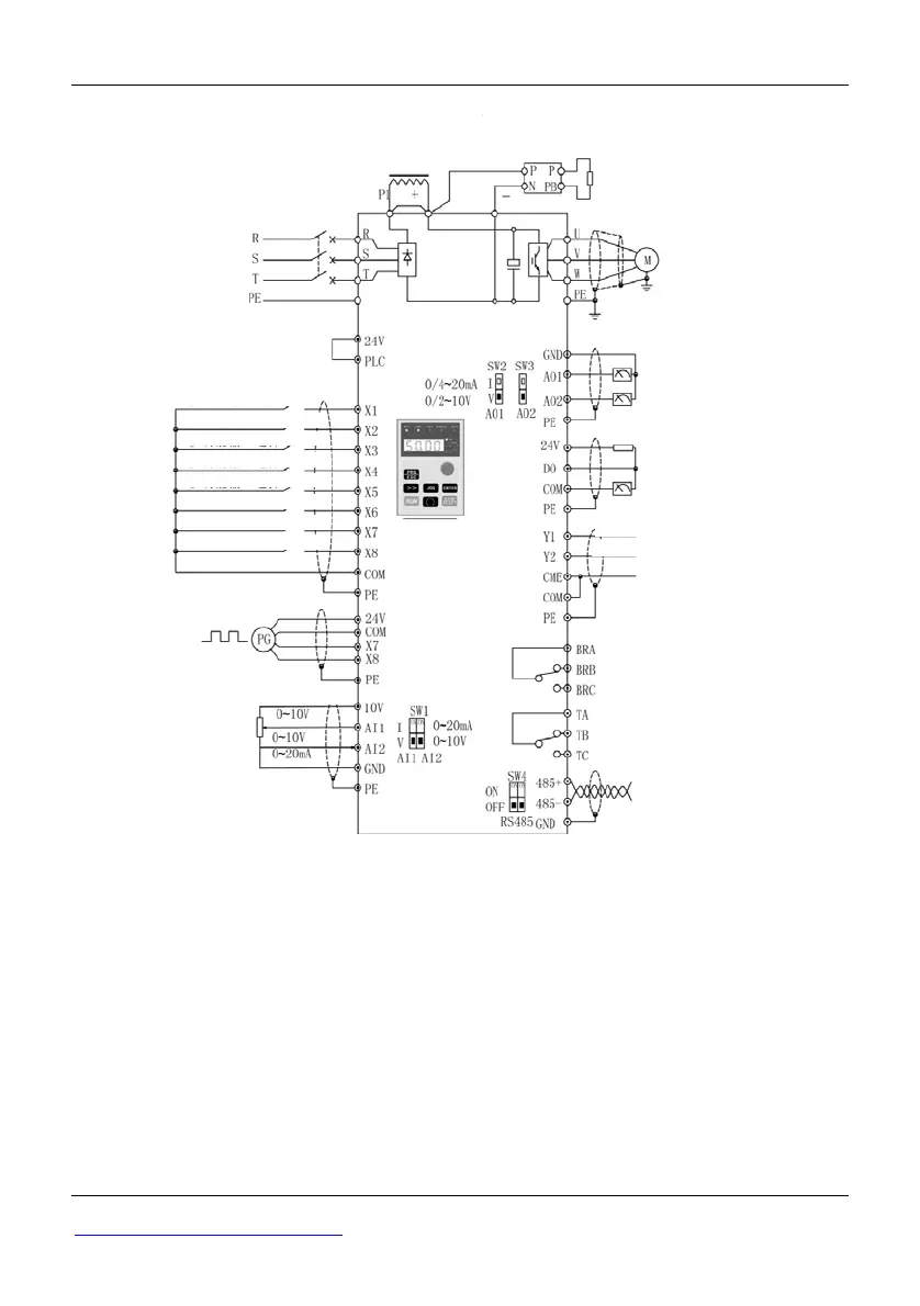
Fig 2-35 3018G/3022P~3500G Wiring diagram
Notes:
1. Analog signal input to AI1/AI2 (voltage or current) can be selected by
Data-chosen-switch, the default is voltage input. You can refer P4.00~P4.10 to
set the range.
2. Max output current of control circuit terminal 10 V is 30 mA.
3. The cable between PLC and 24 V terminals should be connected firmly
(S2R4GB~3004GB should be sure to disconnect the cable JP1 between PLC and
24 V; 35R5GB/37R5PB~3500G should be sure to disconnect the cable between
PLC and 24V), otherwise input terminals X1-X8 couldn’t work properly(in