43
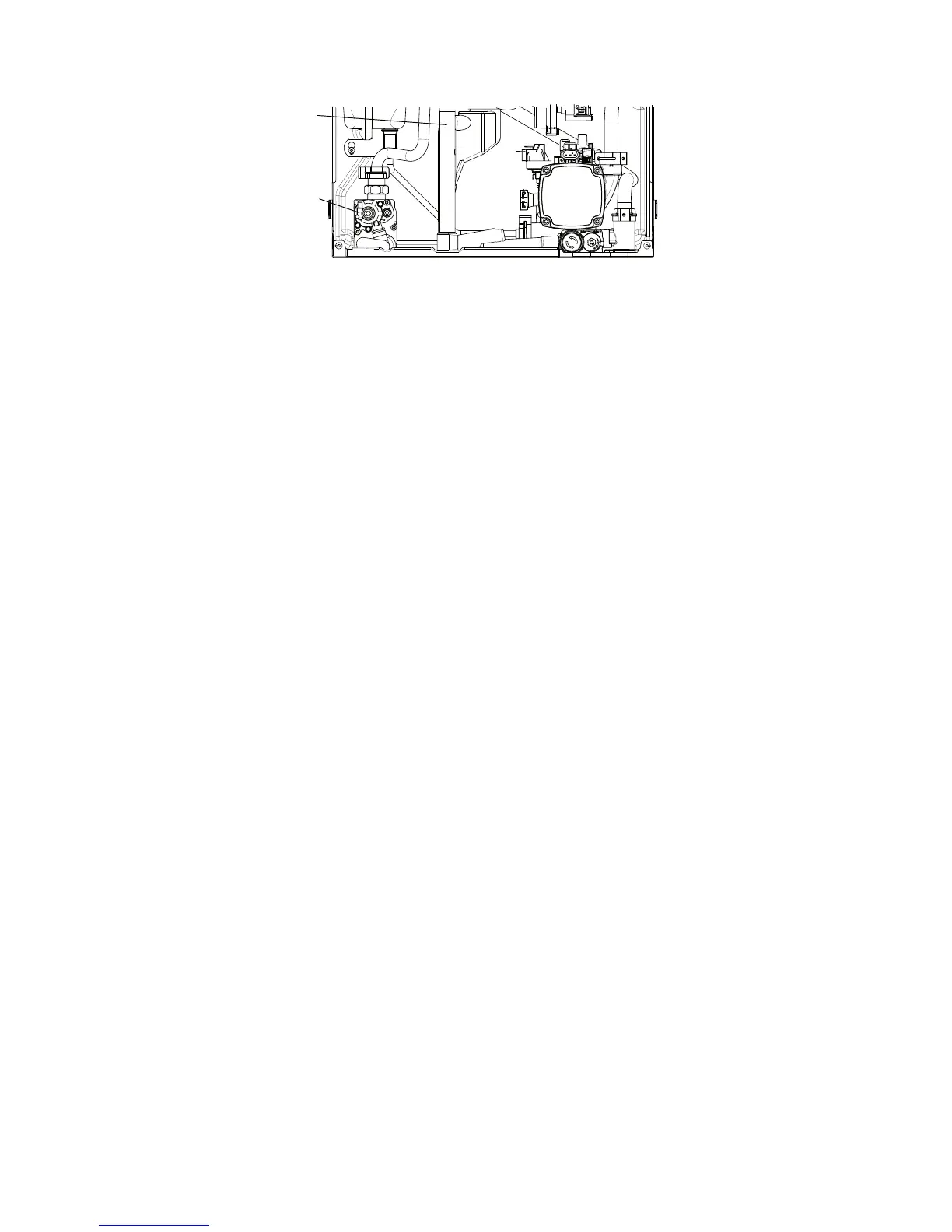
Fig. 7.2
Alpha E-Tec S 20 and 30 - Component Replacement
7.11 PRIMARY HEAT EXCHANGER - Fig. 6.6
Gain access and drain the boiler heating circuit as described in Sections 7.1 and 7.2.
1. Remove the condensate trap assembly as described in Section 7.10.
2. Remove the burner as described in Section 6.3.
3. Unplug the connection from the flue temperature sensor and remove the sensor as described in Section 7.6.
4. Disconnect the condensate drain pipe by pulling its rubber connector from the heat exchanger.
5. Unscrew the flue sampling point cap and remove the complete fitting from the top of the case.
6. Disconnect the flue sensor wires and remove the lower retaining screw on the bottom of the heat exchanger..
7. Remove the heating flow and return pipe retaining clips from the primary heat exchanger and pull the pipes downwards
from the heat exchanger connections.
8. Lift the heat exchanger upwards and forwards to disconnect it from the bottom bracket and withdraw it from the boiler.
9. Refit the flue temperature sensor.
10. Reassemble in reverse order using the lubricant supplied with the heat exchanger kit.
Note: Lubricating the seals with soap and water will aid assembly.
11. Refill boiler, pressurise the system and visually inspect for leaks.
12. Test the boiler, check the ignition and test the combustion as described in Section 6.
7.12 PRESSURE GAUGE - Fig. 7.1
Gain access and drain the heating circuit as described in Sections 7.1 and 7.2.
1. Depress the two lugs on the pressure gauge and pull it out of the control panel.
2. Withdraw the retaining clip securing the pressure gauge sensor (just to the left of the automatic air vent) and withdraw
the sensor.
Note: This is a direct sensor, ensure all electrical components are protected from water escape.
3. Remove the main cable grommet in the bottom panel and remove the sensor tube.
4. Fit the new gauge sensor using a new 'O' ring on the connection if necessary.
5. Reassemble in reverse order.
6. Refill and pressurise the system. (Refer to Commissioning, Section 5.1).
Condensate trap
Gas valve