45
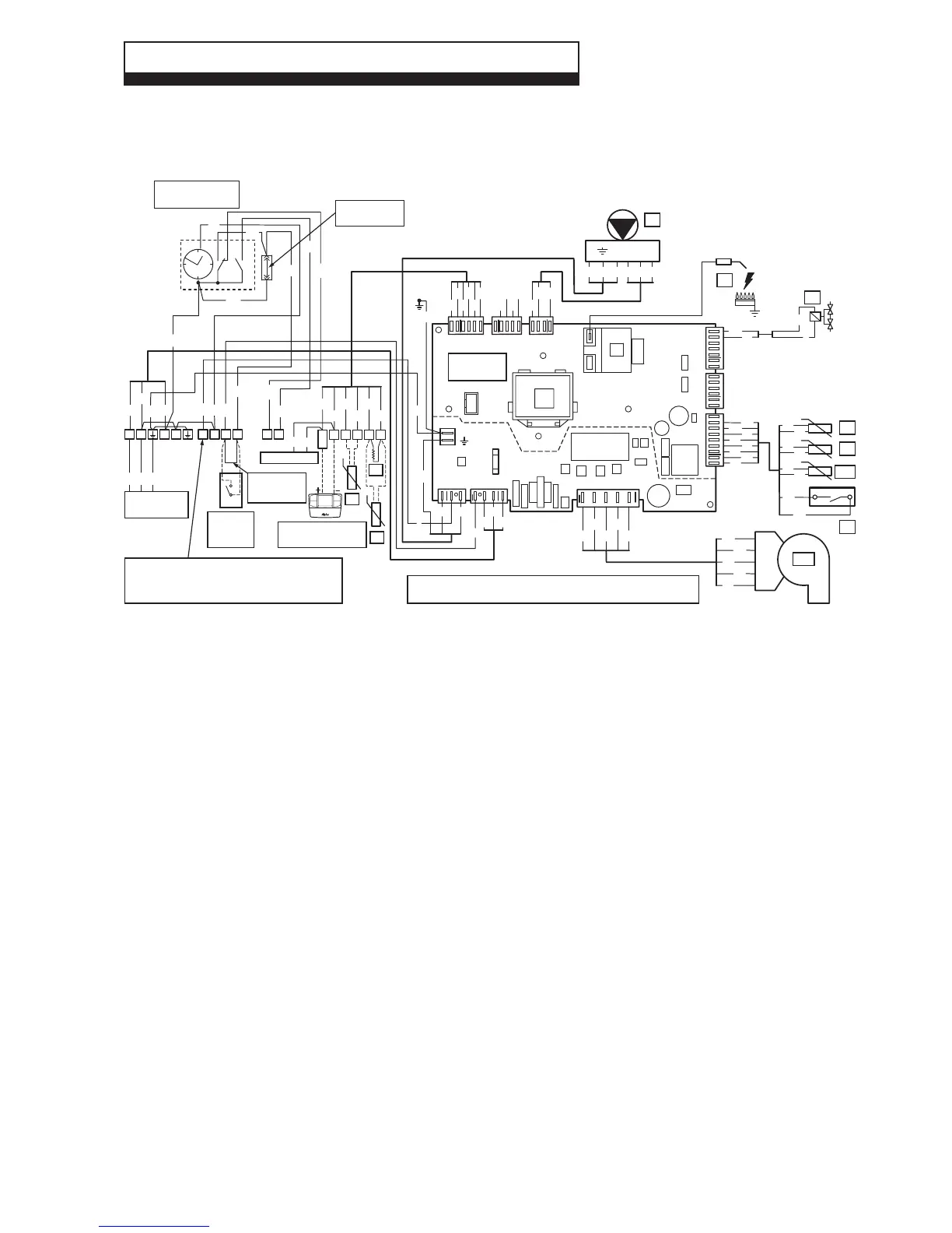
8.1 ILLUSTRATED WIRING DIAGRAM
8 WIRING DIAGRAM
Alpha E-Tec S 20 and 30 - Wiring Diagrams
Colour Code
Bk ......Black
Bl .......Blue
Br ....... Brown
G ........Green
Gy ...... Grey
G/Y ....Green/Yellow
Or.......Orange
P ........Purple
R ........ Red
W ......White
Y ........Yellow
Component identification
B1 ............Flow sensor
B4 ............External sensor (optional)
B5 ............Return sensor
B9 ............Cylinder sensor (optional)
B10 ..........Flue sensor
E3 ............Ignition and detection electrode
M1............Boiler pump
M20..........Fan
M30..........3-way valve motor
R8 ............Cylinder resistor (optional)*
S4 ............DHW flow switch
S5 ............System pressure switch
T2 ............Ignition transformer
Y1 ............Gas valve
Low voltage
connections
220 V
connections
M1
Y
BrG/Y
Bk
PWM
GND
FEED
BlBr
LN
Y1
E3
6
1
9
1
W
P
Or
R
W
Or
P
R
W
W
P
P
Fuse
3.15 AF
-Vcc
HS
+UB
GND
+Vcc
M20
Bl
W
R
Bk
Br
Br R
Bl
W
Bk
1
5
X4
J2 J3
X2
X3
X1
X6
X5
161
5
4
1
7
1
41
XF1
T2
Bl
Br
Bk
J1
3
1
Bl
R
Br
Bk
YBr
Bk
R
Y
Y
Or
Or
P
P
B1
B5
B10
R
W
R
W
S5
Or
Or
G/Y
G/Y
G/Y
Remove link to
connect 220 V
room thermostat
When an Alpha Climatic control is connected to terminals 41 and 44
remove the links between terminal blocks 1 and 2
B4
R
Or
Y
Bk Or Y
Mains Supply
220 V ~ 50 Hz
Br
Bl G/Y
44
40
41
38 39 38 48
For testing only
Bk
R
Chassis
earth
Room
thermostat
(optional)
R
Y
B9
R8
Programmer clock
(optional)
Remove link to
connect clock
Bk
Bk
Bl
Br
Br
Gy
W
2
1
34
5
Ch 1
Ch 2
Alpha Climatic Control
(optional)
Alpha Diverter Valve to be used with Alpha Climatic Control
Configurable relay Parameter P3=5
CH ON contact closed CH OFF contact open
6=Neutral 5=Live (CH ON)
Bk
W
R
Gy
BlBk
Bl
Br
G/Y
G/Y
L
N
A
B
5
6
1
2
4
3
Y
Bl
Bl
DHW ON
DHW OFF
CH
L
L
N
N