8
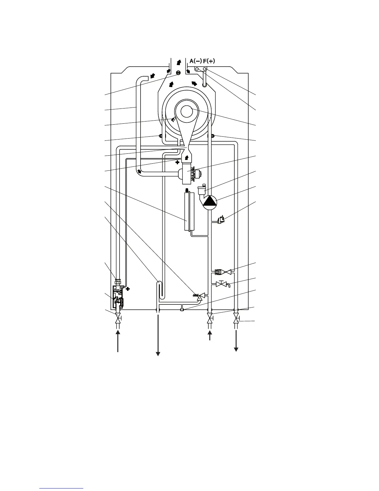
2.7 BOILER SCHEMATIC
Fig. 2.4
Alpha E-Tec S 20 and 30 - Technical Data
1 Gas isolation valve
2 Gas valve
3 Gas injector
4 Condensate trap
5 3 bar safety valve
6 Expansion vessel
7 Venturi positive pressure point (+)
8 Venturi
9 Primary flow temperature sensor
10 Ignition/sensing electrode
11 Air supply pipe
12 Flue temperature sensor
13 Flue test point (pressure point +)
14 Air test point (pressure point -)
15 Burner
16 Primary return sensor
17 Fan
18 Automatic air vent
19 Boiler pump
20 Primary pressure switch
21 By-pass
22 Drain point
23 Safety valve indicator
24 Heating return isolation valve
25 Heating flow isolation valve
Gas
Condensate discharge
and expansion relief
Primary
Heating
return
Primary
Heating flow
1
2
3
4
5
6
7
8
9
10
11
12
25