13
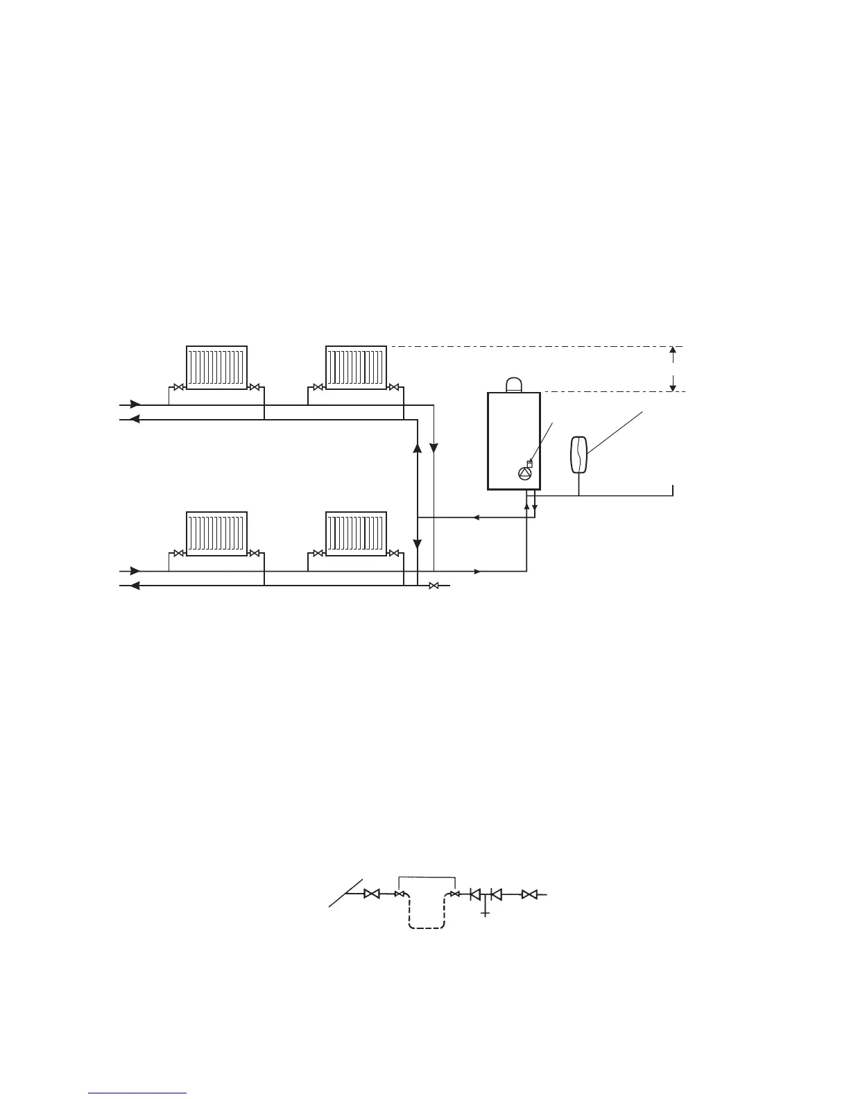
3.7 CENTRAL HEATING SYSTEM - Fig. 3.5
The boiler is designed for use in a sealed central heating system in accordance with the requirements of BS EN 12828 and BS 6798.
The system should be designed to operate with flow temperatures of up to 90°C. When designing the system, the pump
head, expansion vessel size, mean radiator temperature, etc. must all be taken into account. Refer to the pump performance
table for guidelines.
System volume - The expansion vessel incorporated into the boiler is suitable for a sealed heating system with a maximum
water content of 80 litres (18 gal). Above 80 litres, consideration should be given to fitting an additional expansion vessel
fitted in the position shown in Fig. 32.5. To check correct operation of the expansion vessel(s) the system pressure should not
be more than 2.5 bar when the system is at maximum operating temperature (for further guidance refer to BS 7074:1).
The boiler is supplied with the following components built in:-
Pressure gauge - To indicate the system pressure to be maintained.
Expansion vessel - Conforming to EN 13831 with a capacity of 8 litres and pre-charged with air to a pressure of 1.0 bar.
By-pass - The boiler incorporates an automatic by-pass, therefore an automatic by-pass is not required for the system.
3.8 FILLING THE CENTRAL HEATING SYSTEM - Fig. 3.6
The system design pressure (cold) should be set to 1.0 bar. This pressure is equivalent to a static head (see Fig. 3.5) of 10.2
metres of water.
Provision must be made for filling the system. This is done by the use of a filling loop. See Fig. 3.6. A filling loop is not
supplied with this boiler.
Filling of the system must be carried out in a manner approved by the local Water Undertaking. Where allowed, the system
may be filled via a temporary connection as shown in Fig. 3.6. After filling, always disconnect the flexible hose of the filling
loop.
All fittings used in the system must be able to withstand pressures up to 3 bar. Drain taps (to BS 2879) must be used to allow
the system to be completely drained.
Fig. 3.5
Fig. 3.6
Alpha E-Tec S 20 and 30 - General Boiler Information
Filling loop
temporarily connected
Heating circuit
return
Mains
water
supply
Stop
valve
Hose
unions
Stop
valve
Double check
valve assembly
Test cock
Automatic
air vent
Additional expansion
vessel (if required)
Filling point
Static head of system
Heating return
System
drain tap
Heating flow
Note: A drain tap should be installed at the lowest
point of the heating circuit and beneath the appliance.
Boiler