EasyManua.ls Logo

Alpine 7516M User Manual

Alpine 7516M
66 pages
To Next Page IconTo Next Page
Page #1 background imageLoading...
Page #1 background image
Pa
le
“)
ALPINE
ssivice
FM/MW/LW
Cassette
Receiver
CyY
Snhwucttie
Controller
@
For
the
cassette
deck
mechanism
parts
(GR75L02Y)
of
this
model,
refer
to
the
Service
Manual
«
GR/GR-Y
Series
(68P20504W04).
Apne.
op
[Lt
|B
eGon
fF
are
@ee
ir
Ee
Ss
from
GEG
tht
I.
ssc
a
Be
M.S.DXM.1.X.
STMORPT
ALL
SEEK
A.MEMO
AUTO
METAL
BI-LEVEL
25W+25W
7516M
@
Zo
GIVI
aeZoNGIMIMiVaeZou
Ge
Question and Answer IconNeed help?

Do you have a question about the Alpine 7516M and is the answer not in the manual?

Alpine 7516M Specifications

General IconGeneral
BrandAlpine
Model7516M
CategoryCar Receiver
LanguageEnglish

Summary

Alpine 7516M/7516MM/7516L Service Manual

Specifications Overview

FM, MW, LW, and Tape Player Specifications

Detailed technical specifications for FM, MW, LW radio and tape player functions.

General Unit Specifications

General specifications including power, output, dimensions, and weight.

Error Indication for CD Shuttle

Model Specific Features and Controls (7516M/7516MM)

Features Overview

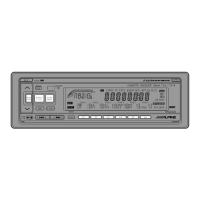
Key features exclusive to the 7516M/7516MM models.

Controls and Indicators Identification

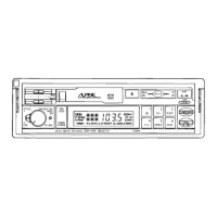
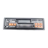
Identification and description of controls and indicators for 7516M/7516MM models.

Model Specific Features and Controls (7516L)

Features Overview

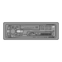
Key features exclusive to the 7516L model.

Controls and Indicators Identification

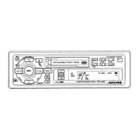
Identification and description of controls and indicators for the 7516L model.

System Connections Diagram

Operation

Basic Operation and Controls

Initial setup, power, volume, and control adjustments.

Radio Operation Modes

Tuning, band selection, memory presets, and special radio modes.

Tape Player Operations

Playback, loading, eject, and special tape functions.

CD Player Operation

CD playback, pause, and special CD functions.

SDK Section Operation

Operation for traffic information reception.

Advanced Tape and CD Functions

Advanced operations like repeat, scan, and random play.

Safety Precautions

System Block Diagram

Disassembly Procedures

Nosepiece and Cassette Deck Removal

Step-by-step guide to removing the nosepiece and cassette deck from the unit.

P.C. Board Removal Steps

Procedures for removing the front and main printed circuit boards.

Adjustment Procedures Overview

FM Section Adjustments

Adjustment procedures for the FM tuner section, including dummy antenna and connections.

FM Section Specific Adjustments

Detailed steps for IF, Noise Level, Seek Stop, VCO, and Stereo Separation adjustments.

SDK Section Setup

Setup for SDK section adjustments: dummy antenna and connections.

SDK Section Adjustments

Procedures for adjusting SK, DK, and output levels in the SDK section.

Tape Player Section Adjustments

Setup and adjustment procedures for tape player head azimuth, Dolby level, and tape speed.

Component Adjustment Locations

Electrical Inspection Specifications

Measuring Conditions and FM Inspection

Conditions for inspection and specific tests for FM reception.

MW and LW Inspection

Specific inspection tests for MW and LW radio reception.

SDK and Tape Inspection

Inspection procedures for SDK function and tape playback performance.

Operational Checks

Radio Operation Checks

Checklist for verifying radio functions including tuning, presets, and modes.

Tape Operation Checks

Steps to verify tape player functions like FF, REW, and playback modes.

CD Shuttle Combination Checks

Verification steps for CD player interaction with other modes.

BA801 Voltage Check

Procedure to check the voltage level of the BA801 component.

Integrated Circuit (IC) Terminal Descriptions

IC501 (35044W01) Terminal Details

Description of terminal functions for the AN7465S integrated circuit.

Tuner Schematic Diagram

FL Display Pinout

Parts Layout - Main P.C. Board (1/2)

Parts Layout - P.C. Boards (2/2)

Schematic Diagram - Part 1

Schematic Diagram - Part 2

Schematic Diagram - Part 3

Schematic Diagram - Part 4

Electrical Parts List

Cabinet Assembly Parts List

Exploded View of Unit Assembly

Semi-Conductor Lead Identifications

IC001 (µPC1675G) Lead Identification

Lead identification for the µPC1675G integrated circuit.

IC051 (AN7465S) Lead Identification

Lead identification for the AN7465S integrated circuit.

IC201 (M51143AL) Lead Identification

Lead identification for the M51143AL integrated circuit.

IC052 (NJM2904M) Lead Identification

Lead identification for the NJM2904M integrated circuit.

IC101 (TDA1579T) Lead Identification

Lead identification for the TDA1579T integrated circuit.

IC301 (TA8221H) Lead Identification

Lead identification for the TA8221H integrated circuit.

BA4560F ICs Lead Identification

Lead identification for BA4560F integrated circuits.

IC401 (MC14014BFEL) Lead Identification

Lead identification for the MC14014BFEL integrated circuit.

IC402 (LC7582A) Lead Identification

Lead identification for the LC7582A integrated circuit.

Related product manuals