13
Alpine Supply Company 42 Direct Vent Gas Fireplace
ELECTRICAL SYSTEM
INSTALLING ELECTRICAL CONTROLS
AND WIRING
A 110 volt power supply (grounded) is required to
operate the optional blower system. The blower
controller (optional) should be mounted in a wall within a
few feet of the appliance, in a convenient location. Once
the location of the blower controller has been identified,
mount a metal or plastic electrical box and route the
wires from the blower to the electrical box. The wiring
needs to be routed from the control location to the
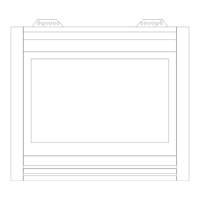
appliance. The appliance internal electrical box is located
on the right side of the appliance. (See figure 9). Use only
Blower Kit #431917 Installation instructions for the
blower kit are included with the kit.
NOTE: even if the blower is not purchased with the unit,
it is still a good idea to hardwire the appliance in case the
fan is installed at a later date.
DO NOT LEAVE THIS
CONNECTION LIVE UNTIL THE FAN IS
INSTALLED.
Fig. 9 – Typical Electrical
NOTE: Proper grounding must be maintained on the
appliance and on the blower assembly.
NOTE: Do not allow any wiring to rest against the
appliance as fire danger may result.
NOTE: DO NOT connect any electricity to the main
gas control valve wiring. Valve damage will certainly
occur.
The appliance is equipped with a millivolt system that
controls the main gas control valve. A low voltage two
strand wire set needs to be routed from the main gas
control valve to the desired position of the wall switch.
Some prefer the switch be co-located with the blower
controller. If this choice is made, a DIVIDED double
gang electrical box must be installed. (A standard (non-
divided) double gang box cannot be used.)
When installing the low voltage wiring. It is essential that
the wires be marked so as to never have 110 volt /24 volt
power attached to them. If power is attached to the
control valve, damage will certainly occur.
The appliance generates the millivoltage needed to
operate the gas control system. A standard wall toggle
switch or a listed wall thermostat may be used to control
the main gas valve.
The millivolt system has limitations on the distance it can
be installed from the fireplace. The greater the distance
from the fireplace, the larger the wire size must be to
prevent loss of the millivoltage. See the table below for
recommendations.
Maximum Length
Wire Guage
9’ 22 ga.
13’ 20 ga.
20’ 18 ga.
30’ 16 ga.
50’ 14 ga.
Millivolt thermostats and remote controlled millivolt
thermostats are available from your Alpine dealer.
See figures 10, 11 and 12 for additional information
about wiring your appliance.
Note: Local codes need to be followed when installing
any electrical appliance. If conflicts between this
manual and local electrical codes exist. Local codes
always prevail.
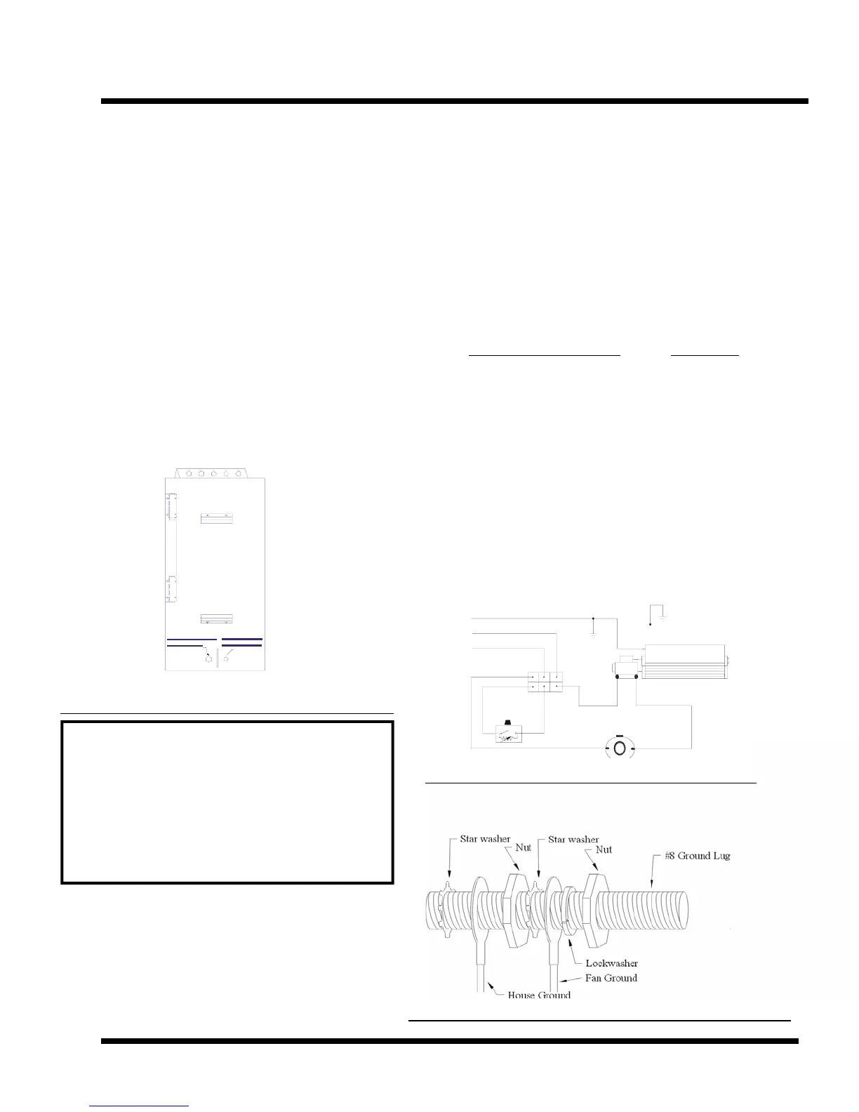
______Fig. 11 – Proper Grounding Technique_______
Green (Ground)
White (Neutral)
Black (Live)
Fan
White
Green
Black
Black
White
120 VAC
60HZ
(*by others)
(*by ot hers)
(*by ot hers)
ON
OFF
Thermodisc
(*Supplied by others
install according to
local code)
Ground for
mobile home
Fig. 10– Wiring Schematic