4
Alpine Supply Company 42 Direct Vent Gas Fireplace
SYSTEM SPECIFICATIONS
Burner Inlet Orifice Sizes:
(2500 TO 6500 feet altitude )
Natural Gas: #43 Propane: #55
Max. Input Rating – Natural Gas 26,000 Btu/h
Propane 23,000 Btu/h
Min. Input Rating – Natural Gas 13,400 Btu/h
Propane 16,000 Btu/h
Min. Supply Pressure Natural Gas 5.0” w.c.
Propane 11.0” w.c.
Max. Supply Pressure Natural Gas 7.0” w.c.
Propane 13.0” w.c.
Manifold Pressure
Natural Gas 3.5” +/-0.2” w.c.
Propane 10” +/-0.2” w.c.
Minimum Gas Line Pipe Size: 1/2”
Electrical: 120 V.A.C. System
(Optional blower) Amperage Rating: 0.62 Amps
Venting: Simpson Duravent Direct Vent (4” x 6 5/8”)
Must use high wind termination on vertical
applications (Simpson part # 0991)
DERATING THE BURNER
The fireplace has been designed to operate at elevations
approximately 4500 ft. above sea level. No deration of
the burner needs to occur unless the fireplace is installed
at elevations below 2500 ft. or above 6500 ft. The burner
orifice should then be adjusted one drill size smaller for
higher elevations and one drill size larger for lower
elevations.
INSTALLATION REQUIREMENTS
3) If the appliance is to be installed on carpeting,
combustible vinyl tiling, or any other combustible
surface other than wood flooring, a 1/2” wood panel
must be installed on top of the existing flooring. The
panel must extend the full width and depth of
appliance.
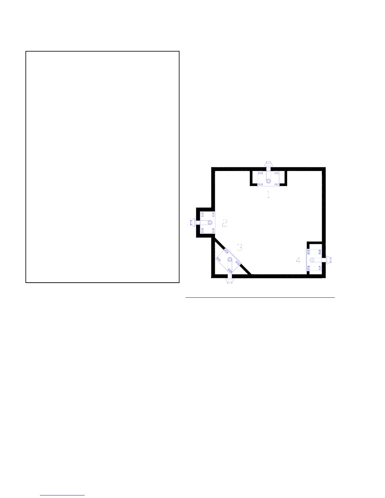
4) The ASC-42 fireplace can be installed into many
different applications. See Figure 1 for examples.
5) Lay out fireplace dimensions on installation site
before proceeding with installation. This will ensure
proper clearances and assist in identifying potential
problems before installation.
6) Make sure to review the vent termination system
requirements before proceeding.
Fig. 1 – Installation Placement Options
LOCATING THE FIREPLACE
1) When selecting a location for your Gas Fireplace,
ensure that the clearances outlined in this manual are
adhered to strictly.
2) The fireplace must be installed on a flat, solid,
continuous surface. If the appliance is to be raised
off the floor on a platform, it must be securely
fastened to a sturdily constructed platform.
GAS LINE INSTALLATION
IMPORTANT: Gas piping should be installed only by
trained and qualified technicians.
The appliance and its individual shut off valve must be
disconnected from the gas supply piping system during
any pressure testing of that system in excess of 1/2” psi.
The appliance must be isolated from the gas supply pip-
ing system by closing its individual shutoff valve during
any pressure testing of the gas supply piping system at
test pressures equal to or less than 1/2” psi.
The gas line must be brought through the left side of the
appliance. The 1/2” service gas line must connect to the
flexible appliance connector which is attached to the
main control valve. DO NOT MAKE THIS CONNEC-
TION UNTIL ALL PRESSURE TESTING OF THE
GAS PIPING SYSTEM IS COMPLETE. FAILURE
TO DO SO WILL RESULT IN DAMAGE TO THE
MAIN CONTROL VALVE.
( Continued on next page )