16
Alpine Supply Company 42 Direct Vent Gas Fireplace
VERTICAL TERMINATION
1. Maintain the 1” clearances to combustibles when
passing through ceilings, roofs, enclosures, attic rafters,
or other nearby combustible surfaces. Do not pack air
spaces with insulation. See the diagrams on page 11 of
this manual for the maximum vertical rise of the venting
and the maximum horizontal offset limitations.
2. With the gas appliance in its desired location, drop a
plumb bob from the ceiling to the position of the
appliance flue exit and mark the location where the vent
will penetrate the ceiling. Drill a small hole at this point.
Next, drop a plumb bob from the roof to the hole
previously drilled in the ceiling and mark the spot where
the vent will penetrate the roof. Determine if ceiling
joists, roof rafters, or other framing will obstruct the
venting system. You may chose to relocate the fireplace
or offset the venting to avoid cutting framing members
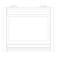
(see figures 19 and 20).
Firestop
Flashing
Fig. 19– Vertical Venting
45 degree
Elbow
Wall Strap
Plumbers Tape
Firestop
Fig. 20– Venting Offsets
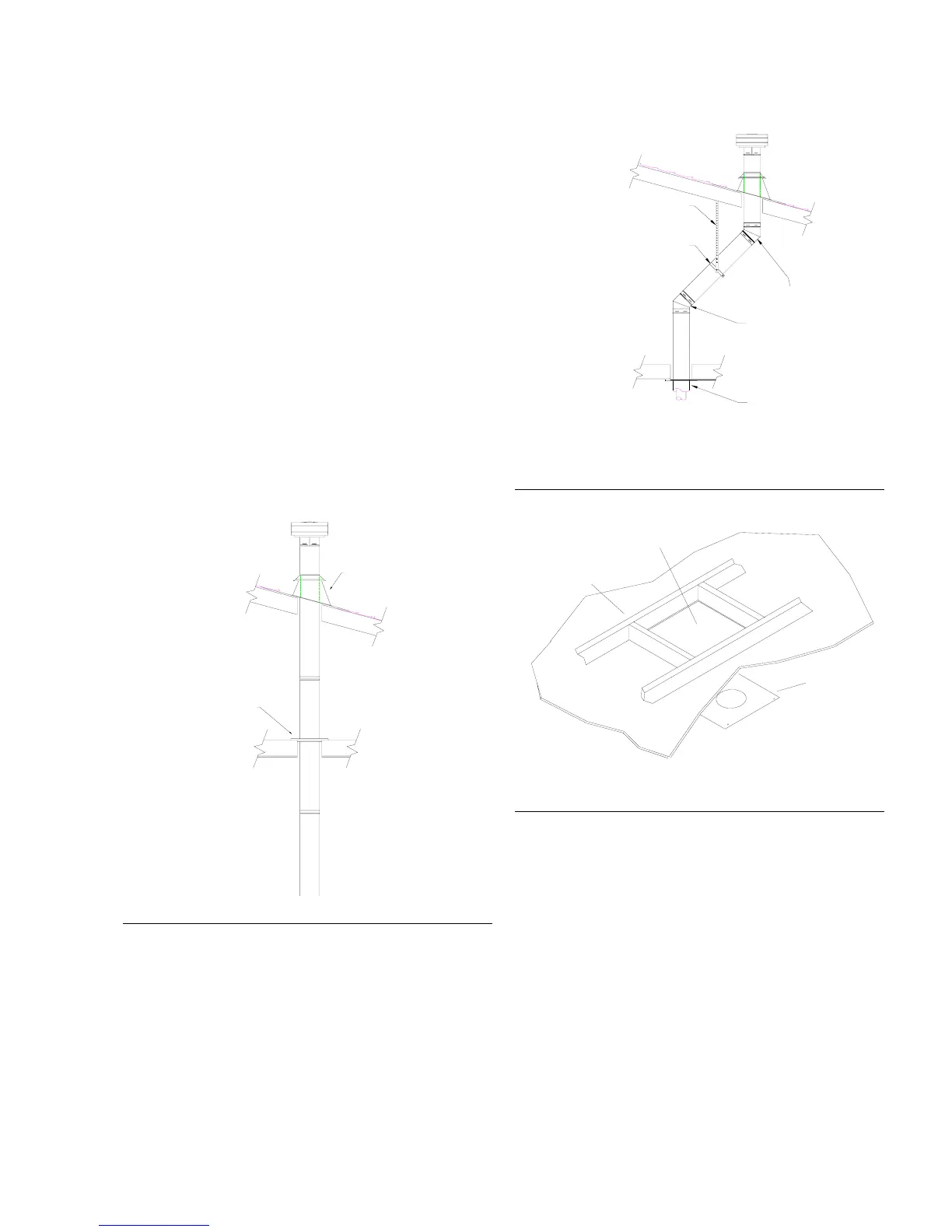
3. A Firestop spacer must be installed in the floor or
ceiling of every level. To install the Firestop spacer in a
flat ceiling or wall, cut a 10 inch square hole. Frame the
hole as shown in Figure 21 and install the firestop.
4. Assemble the desired lengths of pipe and elbows.
Ensure that all pipes and elbow connections are in the
fully twist–locked position and sealed with Mill-Pac
brand sealant on the inside collar and aluminum tape on
the exterior. An air tight must be created.
Firestop
Spacer
Framing
10" x 10" Square
Hole
Fig. 21– Firestop Installation
5. Cut a hole in the roof centered on the small drilled hole
placed in the roof in Step 2. The hole should be of
sufficient size to meet the minimum requirements for
clearance to combustibles of 1”.
6. Continue to complete the assembly of the pipe lengths.
See figure 22 for proper vent height projecting through
the roof.
7. Ensure that the vent is vertical and secure the base of
the flashing with roofing nails. Slide the storm collar over
the pipe section and seal with a mastic type sealant.
8. Install the vent cap by twist locking it in place.
See Offset Table on page 11 for additional offset details.