15
Alpine Supply Company 42 Direct Vent Gas Fireplace
INSTALLATION INSTRUCTIONS
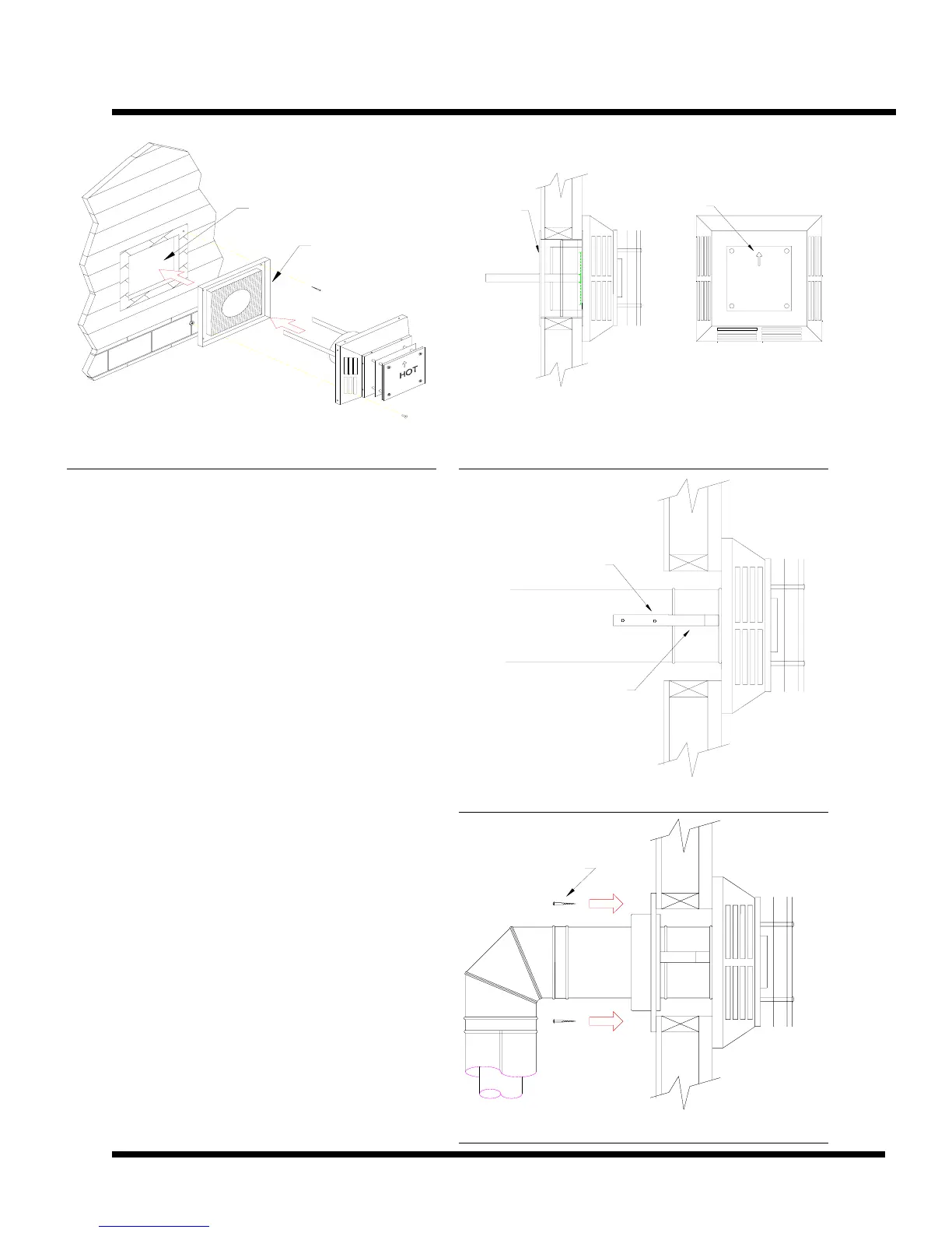
11" x 11" Opening
Vinyl Siding Stand-off
Fig. 15– Termination Framing
NOTE: The arrow located on the face of the
termination must be pointing up.
NOTE: Clearances to combustibles from the vent pipe
must be adhered to. See the table below for proper
clearances.
Horizontal Venting Clearances
TOP OF PIPE 2” to combustibles
SIDES OF PIPE 1” to combustibles
BOTTOM OF PIPE 1/2” to combustibles
NOTE: IF installing termination on a siding covered
wall, a vinyl standoff or furring strips must be used to
ensure that the termination is not recessed into the
siding.
4. Before connecting the horizontal run of vent pipe to
the vent termination, slide the Wall Penetration Heat
Shield over the vent pipe (see figure 16, 18).
5. Slide the appliance and vent assembly towards the
wall, carefully inserting the vent pipe into the vent cap
assembly. The vent pipe must extend into the vent cap,
resulting in minimum pipe overlap of 1-1/4 inches.
Secure the connection between the vent pipe and the vent
cap by attaching the two sheet metal strips that extend
from the vent cap assembly into the outer wall of the vent
pipe. Use two sheet metal screws to connect the strips to
the pipe section (see figure 17).
Sheet Metal
Screws
Attaching Straps
Fig. 17– Attaching the Termination
Wall Penetration
Heat Shield
Make Sure Arrow
is pointing up.
Fig. 16– Penetration Shield
Wood Screws
Fig. 18– Finishing the Heat Shield