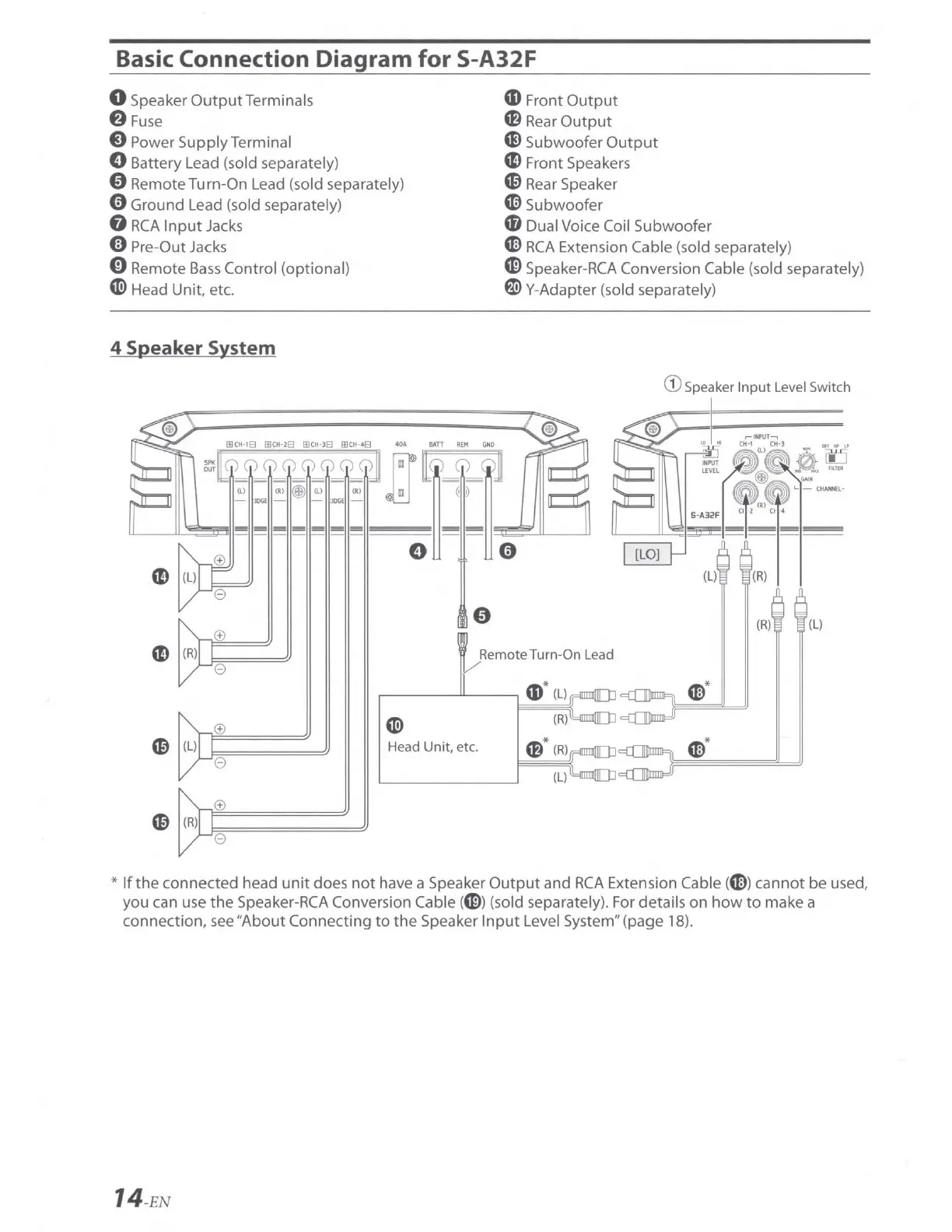
Basic Connection Diagram
for
S-A32F
0 Speaker OutputTerminals
f)
Fu
se
Q Power
Supply
Terminal
0 Battery Lead (sold separately)
0 Remote Turn-On Lead (sold separately)
0 Ground Lead (sold separately)
G
RCA
Input
Jacks
(!) Pre-Out Jacks
0 Remote
Bass
Control (optional)
«i>
Head Unit, etc.
4 Speaker System
CD
(R)
L.J:,;
s===
e
0
e
0
e
«i)
Head
Unit
, etc.
CD
Front
Output
'8
Rear
Output
CE,
Subwoofer
Output
CD
Front Speakers
C0
Rear Speaker
G'l)
Subwoofer
'8 Dual Voice Coil Subwoofer
G>
RCA
Extension Cable (sold separately)
CE,
Speaker-RCA Conversion Cable (sold separately)
f)
Y-Adapter (sold separately)
G)
Speaker
Input
Level Switch
(R)
(L)
Remote Turn-On Lead
a,
*
(L
)
G)
*
(R
)
m*
(R
)
G)*
(L)
*
If
the
connected head
unit
does
not
have a Speaker
Output
and
RCA
Extension Cable
(G))
cannot
be
used,
you can use
the
Speaker-RCA Conversion Cable
(CE))
(sold separately). For details
on
how
to
make a
connection, see "
About
Connecting
to
the
Speaker
Input
Level System" (page 18).
14-EN