Aircraft Systems
ELECTRICAL SYSTEM
AL250 Flight Manual
MEP
6-8-2 BATTERY
The battery switch is a red two-position rocker switch to the left of the alternator
switch. If the battery master switch is off and t he engines are not running, the engines
cannot start and all electric equipment is off.
In case of an alternator failure, or if the alternators are not switched on, the battery
will be deplete d after a few minutes , depending on current power consumption.
Connection of a ground power unit can be simulated by means of the Instructor Station
(Aircraft W indow).
Figure 6.47: Ele ctrical switches
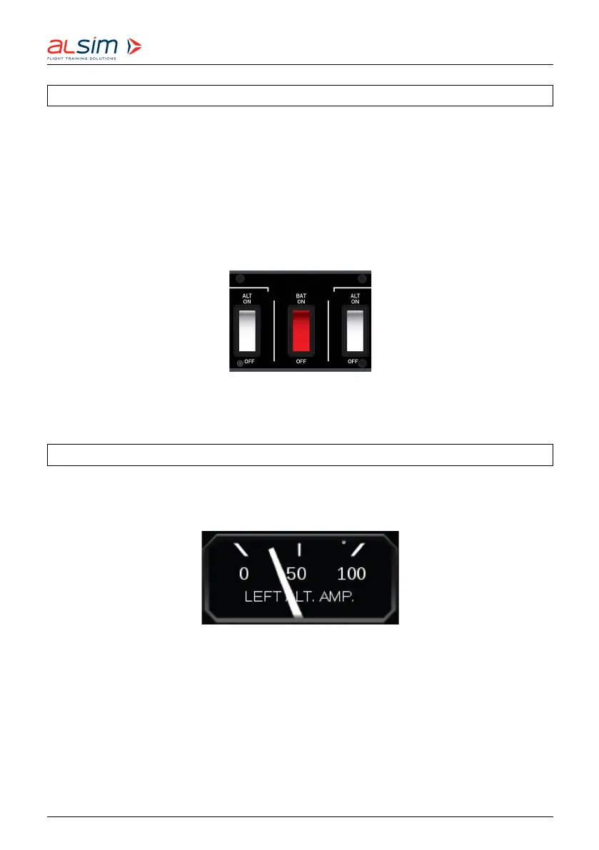
6-8-3 ALTERNATOR AND AMMETER
The alternator switches are next to the battery master switch. Electrical load for the
left and right generator is indicated by ammeters situated on the central flight deck.
Figure 6.48: Ammete r
When the alternator is running, it will provide electric power to the aircraft systems
and charge the battery if necessary. Recharging the battery takes approximately 5
minutes.
Rev. 1.8 © 2021 ALSIM - All Rights Reserved 6-48