Aircraft Systems
POWER PLANT
AL250 Flight Manual
MEP
6-2 POWER PLANT
This chapter is not concerned with the type of engine and propeller installed on the aircraft
b ei ng simulated, nor with how they function. This chapter only deals with how to actuate
the controls and how to read the instruments in the trainer cockpit.
6-2-1 ENGINE AND PROPELLER CONTROLS
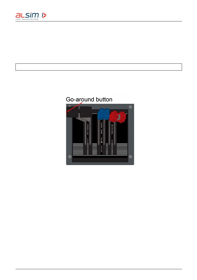
The power levers (black handles), propeller levers (blue handles) and mixture levers (red
handles) are located on the pedestal. The left-hand levers control the left engine, the right-
hand levers the right engine.
Figure 6.7: Power Plant Controls
Pushing the power levers forward increases the manifold pressure.
There is a go-around button on the side of the left power lever handle, pushing this button
will:
• disengage the autopilot
• display the flight director guidance bars for a 7°-climb
• display ‘GO AROUND’ above the ADI.
Pushing the propeller levers forward increases the desired propeller RPM. Pulling the
levers all the way back will feather the propellers (see picture on page 6-11).
Pushing the mixture levers forward increases the richness of the mixture (more fuel,
less air).
Rev. 1.8 © 2021 ALSIM - All Rights Reserved 6-10