6 • Section 3 — Safety
into consideration general material shape, protrusions,
and attached limbs.
Chipper Personnel Safety Devices
Danger
Death or serious injury will result from careless or
improper use of the unit. Do not operate the unit
without proper training.
All personnel using this chipper must be trained and
qualied in all aspects of the operations, maintenance,
repair, and safety procedures dened in this manual
prior to conducting any operations or procedures. All
maintenance personnel and operators shall ensure the
proper operation of each safety device prior to starting
the engine or operating the chipper. Contact Altec Envi-
ronmental Products for replacement parts.
Warning
Death or serious injury can result when operating
this unit. Safety devices are not a substitution for
proper operation. Read the entire manual and all
safety decals and placards.
Panic Bar Assembly
In the event of an unforeseen situation the panic bar
(refer to Figures 3.1 and 3.2) can be activated by pulling
down on bar A or by pulling or pushing bar B towards the
rear of the chipper. This action will stop all movement of
the feed roller.
Figure 3.1 — Panic Bar Assembly
Warning
Death or serious injury can result from unexpected
roller movement. Feed rollers begin movement as
soon as the valve handle is activated. Make sure all
operators are advised prior to your actions and that
the infeed chute is clear of all personnel and tools
before reactivation of the feed system.
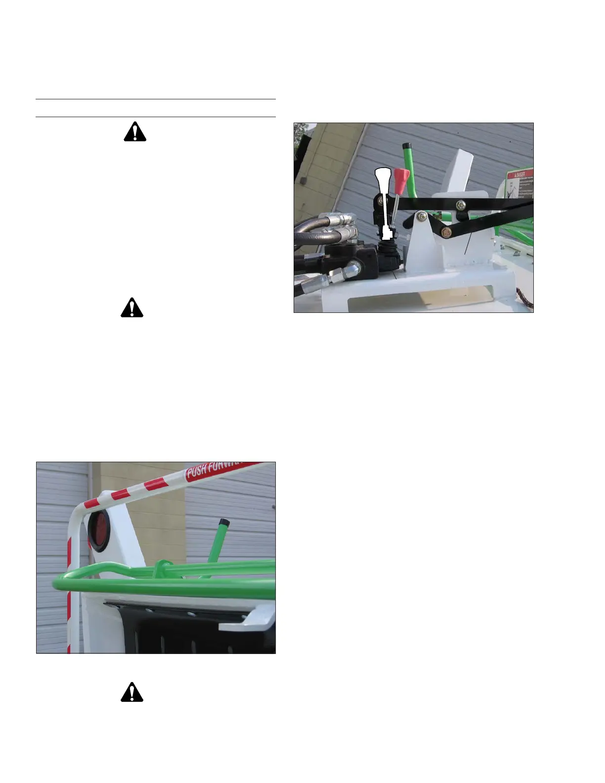
Figure 3.2 — Valve and Bar Linkage
The panic bar assembly consists of two bars (A and B),
the hydraulic valve and the bar linkage. When you pull
down on bar A or push towards the rear of the chipper
on bar B, the bar connecting linkage activates the handle
on the valve. This action stops all movement of the feed
rollers. To continue operation you must manually reset
the handle on the valve to the Run position.
1. Test the panic bar assembly daily and whenever new
personnel are assigned to the chipper.
2. After completing all appropriate safety and operational
checks and with no material in the infeed chute, pull
or push the feed bar to activate the feed roller in the
forward or reverse direction. Visually verify the rota-
tion of the feed roller.
3. Push down on bar A or move bar B.
4. Feed roller movement must stop.
5. If feed rollers do not stop, repair as necessary prior
to operating the chipper.
Chip Curtain
The kickback curtain (refer to Figure 3.3) stops or deects
chips and small debris from leaving the infeed chute
area. This also helps in decreasing the amount of clean
up around the chipper.
Run
Stop
Valve
Bar Linkage
A
B