54 • Section 7 — Maintenance
material will cause the drum rpm to reduce. In the event
that the rpm drop below 2,000 rpm, the control module will
automatically send a signal to the EFC valve and reverse
the rotation of the feed wheel. This will remove the fed
material from the cutting drum and allow the system to
regain speed. During this time, the EFC valve is in the
neutral state. The system will not automatically resume
forward feed until the drum rpm have recovered. This
event occurs quickly and can last less than a second.
Advance System Recovery
Advance system recovery is a secondary security mea-
sure designed to ensure that the wood fed is controlled.
In the event that the EFC cannot reverse the fed material
due to the wood being too short, the advance system
recovery prevents the wood from being pushed into the
cutting mechanism as the feed wheel descends. It also
monitors the drum rpm disabling the fed material from
dropping the drum rpm to the point where the system would
shut down the engine. This ensures longer component
life and more effective performance. The specic compo-
nents involved in the system are the control module, lift
cylinder, holding valve, and the magnetic speed sensor.
Using the magnetic pickup, the control module monitors
the drum rpm. When feeding wood forward, the material
will cause the drum rpm to reduce. In the event that the
fed material cannot be reversed because it is too short, the
feed wheel will advance it forward as it descends about
the pivot point. If the rpm drop below 1,300, the control
module will automatically send a signal to the holding
valve and block the ow of oil from the lift cylinder. This
will prevent the cylinder from descending. The system
will not automatically resume the descend until the drum
rpm have recovered. This event occurs quickly and can
last less than a second.
While the EFC valve will only allow ow to the motor in a
specic rpm range, the lift cylinder can be used any time
that the engine is running. The feed roller assembly can
be lifted up allowing brush or logs to be tethered through,
or lowered down putting pressure and compressing the
fed material. It is important to note that in the descend
of the feed wheel will have a timed delay in the range
between 200 rpm and 1,300 rpm. The system will allow
for upward motion, but will not allow downward motion
until several seconds have passed.
Warning
Death, serious injury, or property damage can result
when attempting to access moving components.
Make sure components have come to a complete
stop before performing inspection or maintenance.
During any point in operation, the panic bar can be pulled
stopping all hydraulic ow to the system. This will divert
all pump ow directly to tank rendering all successive
functions (feed motor, lift cylinder, etc.) disabled. The
panic bar solenoid must be reset in order to resume
system operation.
Troubleshooting
Refer to Figure 7.7 for troubleshooting information.
Drum Magnetic Pickup
Speed (rpm) Frequency (Hz)
500 167
600 200
700 233
800 267
900 300
1,000 333
1,100 367
1,200 400
1,300 433
1,400 467
1,500 500
1,600 533
1,700 567
1,800 600
1,900 633
2,000 667
2,100 700
2,200 733
2,300 767
Figure 7.8 — Frequency to rpm Conversion
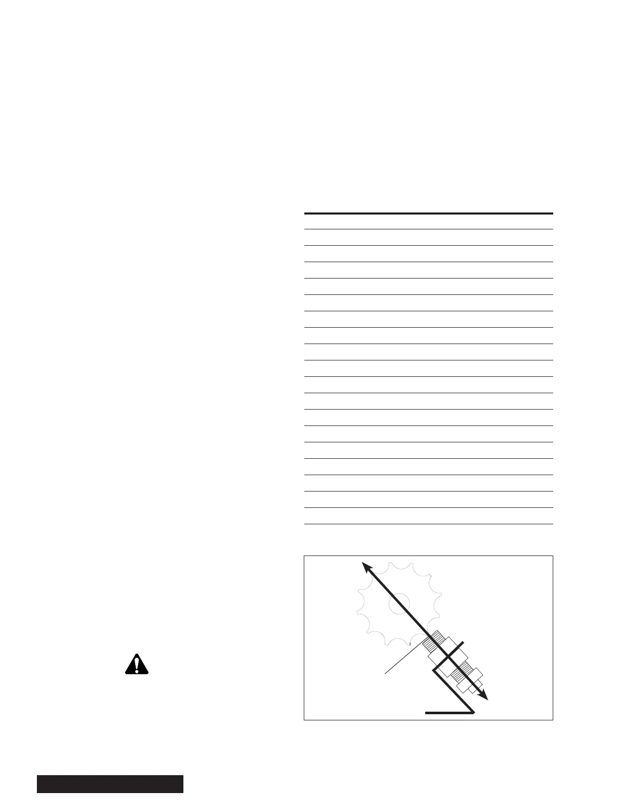
Figure 7.9 — Magnetic Sensor Pickup
C
Measure
Gap Here