Section 5 — Clearing Feed System and Discharge Chute • 31
Section 5 — Clearing Feed System and Discharge Chute
Feed System
Warning
Death or serious injury can result if proper feed roller
clearing procedures are not followed. Only person-
nel that have been properly trained, understand the
dangers, and are authorized by the employer may
perform this operation.
Caution
Injury can result from being pinched or trapped be-
tween moving components. Keep hands clear.
Never attempt to pry open the feed rollers. Rollers must
only be opened using either the lift cylinder or the Altec
Environmental Products supplied jack.
Always be aware of pinch points during the lifting opera-
tion. These dangerous pinch points are changing during
the lifting operation. Never place any part of your body
between the feed rollers.
Extreme care must be taken when removing material or
performing service in the feed roller area.
Never place any part of the body into the feed roller area.
Use a stick or other nonmetallic object to clear this area
of debris.
Extreme care must be taken when removing material or
performing service in the transition chute area. Before
beginning any procedure make sure all movement of the
engine, disc, and feed roller have come to a complete
stop. Remove keys from the ignition and place in pocket.
Complete LOTO procedures.
Always make sure the feed roller assembly is secure
before attempting maintenance in the feed roller/transi-
tion area.
Never reach into or place any part of the body into the
transition chute.
Always use appropriate tools to remove jammed materi-
als. Never reach into the infeed chute.
In the event of material jammed between the feed rollers
and the disc, attempt the following actions before attempt-
ing the mechanical actions contained in this section.
1. Push forward on the control bar to attempt to reverse
the material backward.
2. With the drum at operational speed, attempt to load
another log into the feed rollers. This action may
advance the jammed material.
3. With the drum at operational speed, attempt to load
brush on the top of the jammed material. This action
may advance the jammed material.
4. If equipped with a lift cylinder, raising or lowering the
cylinder may advance the material.
Raising the Feed Roll Assembly
1. Move feed roller control arm to the neutral position.
Make sure the feed rollers have come to a complete
stop.
2. Using the lift cylinder valve, raise the upper feed roll
assembly to its maximum position.
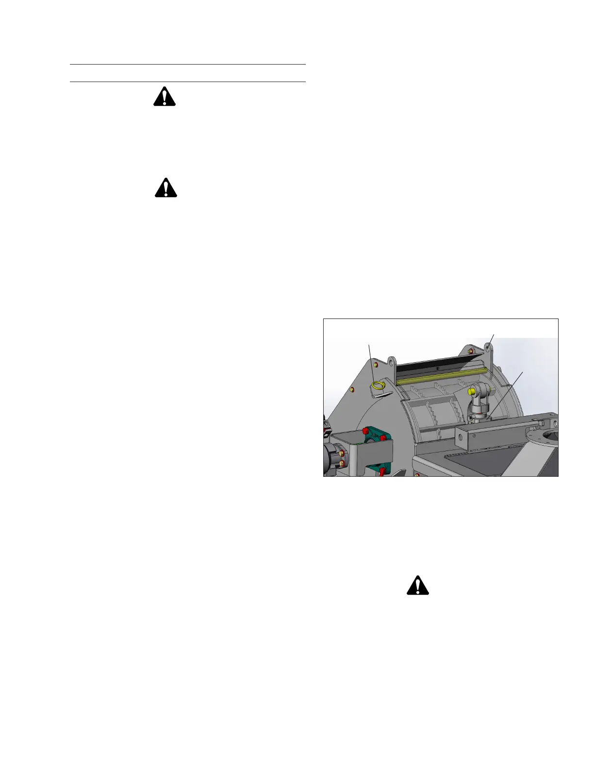
3. Install the upper feed roll lock pin into position (refer
to Figure 5.1).
Figure 5.1 — Feed Roll Lock Pin
4. Turn engine off and remove keys.
5. Remove negative battery cable.
6. Lock battery box.
Warning
Death, serious injury, or property damage can result
when attempting to access moving components.
Make sure components have come to a complete stop
before performing inspection or maintenance.
7. Make sure all movement of drive components and
cutter assembly have come to a complete stop.
8. Using appropriate tools remove any material interfer-
ing with the rotation of the cutter mechanism.
Lock Pin Storage
Location
Feed Roll Lock Pin
in Pinning Location
Feed Roll
Lift Cylinder