29
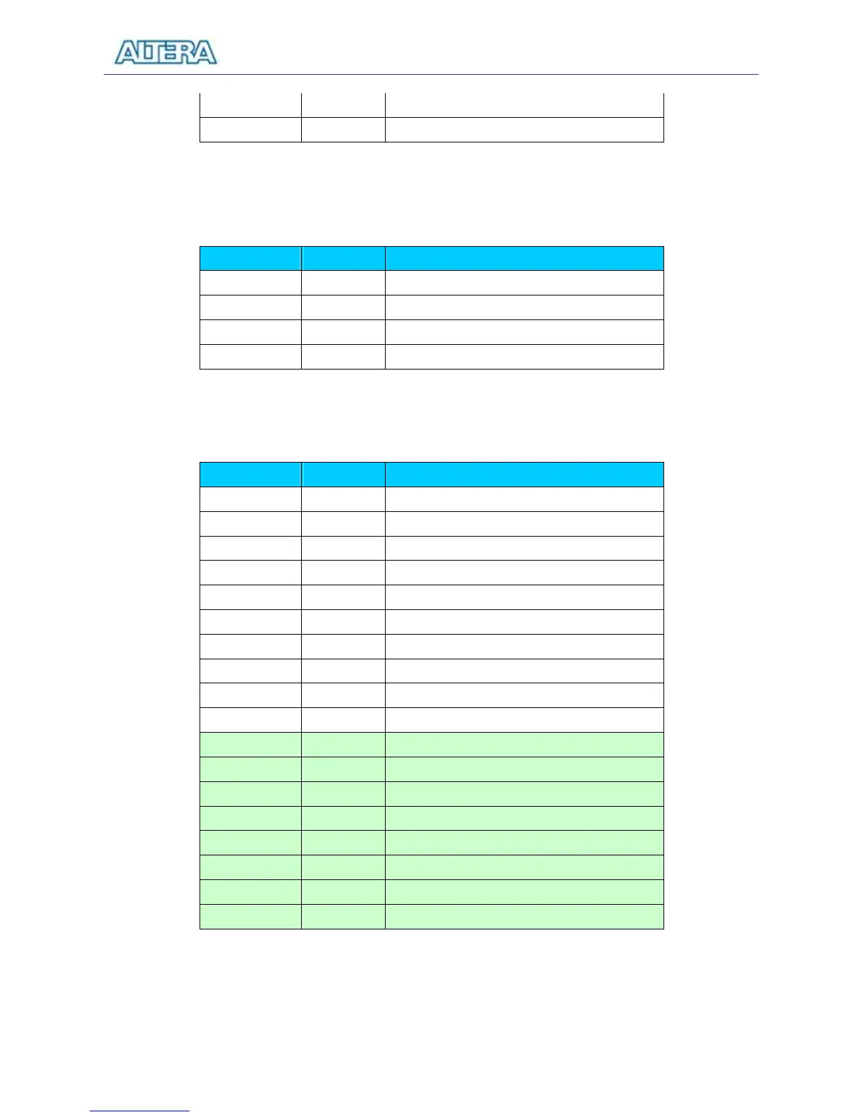
SW[8] PIN_M1 Toggle Switch[8]
SW[9] PIN_L2 Toggle Switch[9]
Table 4.1. Pin assignments for the toggle switches.
Signal Name FPGA Pin No.
Description
KEY[0] PIN_R22 Pushbutton[0]
KEY[1] PIN_R21 Pushbutton[1]
KEY[2] PIN_T22 Pushbutton[2]
KEY[3] PIN_T21 Pushbutton[3]
Table 4.2. Pin assignments for the pushbutton switches.
Signal Name FPGA Pin No.
Description
LEDR[0] PIN_R20 LED Red[0]
LEDR[1] PIN_R19 LED Red[1]
LEDR[2] PIN_U19 LED Red[2]
LEDR[3] PIN_Y19 LED Red[3]
LEDR[4] PIN_T18 LED Red[4]
LEDR[5] PIN_V19 LED Red[5]
LEDR[6] PIN_Y18 LED Red[6]
LEDR[7] PIN_U18 LED Red[7]
LEDR[8] PIN_R18 LED Red[8]
LEDR[9] PIN_R17 LED Red[9]
LEDG[0] PIN_U22 LED Green[0]
LEDG[1] PIN_U21 LED Green[1]
LEDG[2] PIN_V22 LED Green[2]
LEDG[3] PIN_V21 LED Green[3]
LEDG[4] PIN_W22 LED Green[4]
LEDG[5] PIN_W21 LED Green[5]
LEDG[6] PIN_Y22 LED Green[6]
LEDG[7] PIN_Y21 LED Green[7]
Table 4.3. Pin assignments for the LEDs.