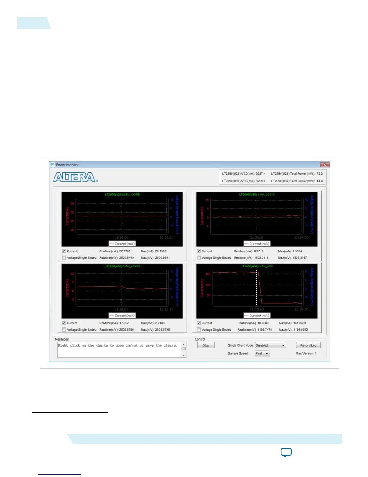
measured current is shown on Altera power monitor GUI when the PowerMonitor.exe is launched. You
will see a current monitor for each of the main supplies to the MAX 10 device as follows:
• 2.5V_CORE
(5)
• 2.5V_VCCIO
• 1.5V_VCCIO
• 1.2V_VCC
For design demonstration purpose, the push button is used for sleep control and the LEDs are used for
sleep status. Thus, these signals have been inverted on the pin level. To enter sleep mode, press and hold
the push button USER_PB0. To release the design to user mode, release the push button USER_PB0.
LED0 indicates the sleep status of the device. LED0 is turned on when the device enters sleep mode and is
turned off when the device is in user mode. During sleep mode, gpio_pad_output ports connecting to
LED1–LED4 are tri-stated and then turned off.
Figure 3-5: Current Monitor for Each Supply
User Mode
Sleep Mode
User Mode Sleep Mode
User Mode Sleep Mode
User Mode Sleep Mode
In sleep mode, all GCLK networks are gated and all output buffers are disabled.
(5)
This is 2.5V_VCCA.
3-6
Hardware Implementation and Current Measurement
UG-M10PWR
2015.11.02
Altera Corporation
Power Management Controller Reference Design
Send Feedback
 Loading...


