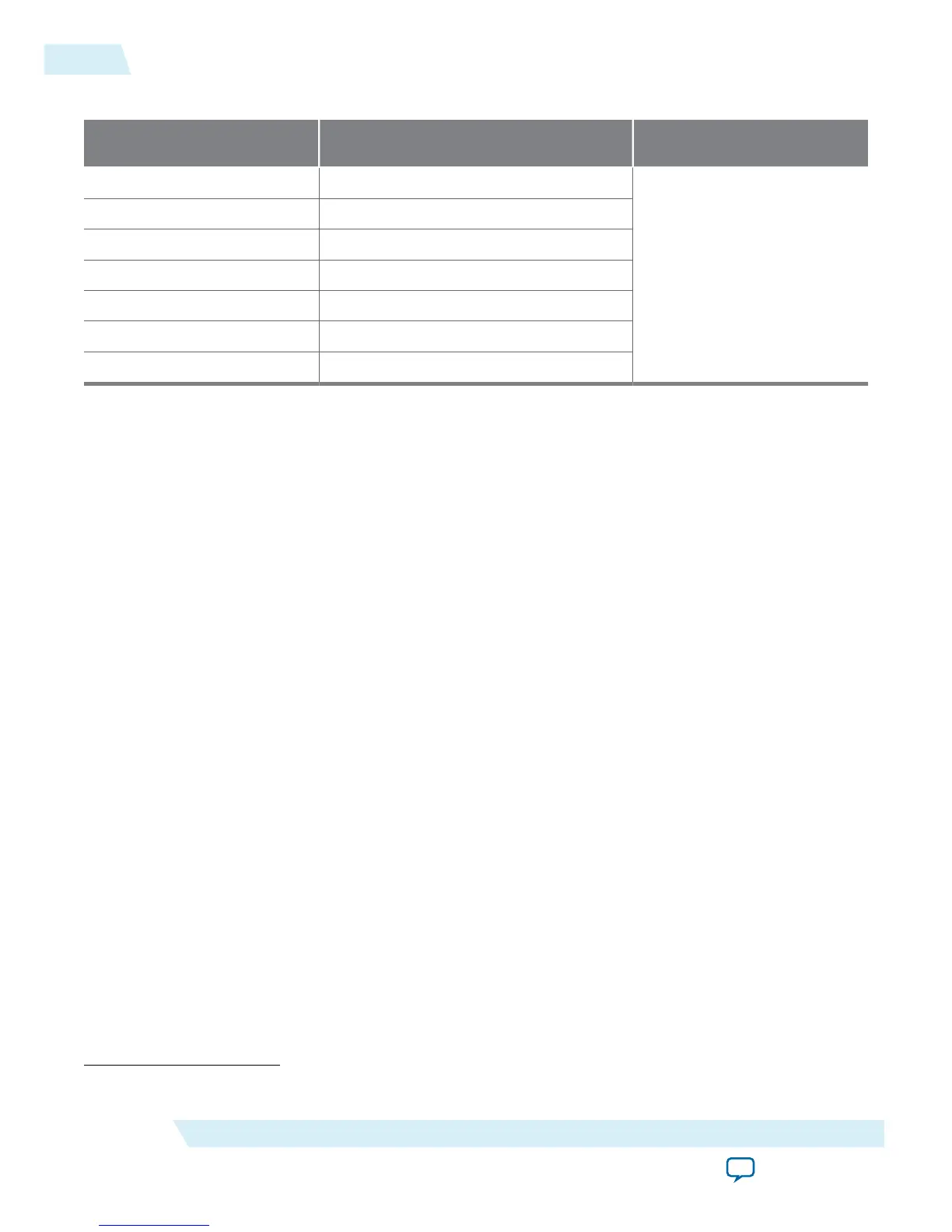
Table 2-3: Maximum V
CCIO
Power Supply Transient Current for MAX 10 Devices
Device Maximum Power Supply Transient Current
(mA)
Duration (s)
10M02 220
25% of the ramp time
10M04 290
10M08 300
10M16 430
10M25 510
10M40 670
10M50 680
Note: The value of the transient current is based on the zero decoupling capacitance on the characteriza‐
tion board. The observed value will be less than the published value after adding the decoupling
capacitance on your design board. Altera recommends using a soft start regulator that is able to
reduce the transient current when the device is powered.
Power-On Reset Circuitry
The POR circuitry keeps the MAX 10 device in the reset state until the POR monitored power supply
outputs are within the recommended operating range of the maximum power supply ramp time, t
RAMP
.
If the ramp time, t
RAMP
, is not met, the MAX 10 device I/O pins and programming registers remain tri-
stated, during which device configuration could fail.
The MAX 10 device POR circuit monitors the following power rails during power up regardless of the
power supply device options:
• V
CC
or regulated V
CC_ONE
• V
CCIO
of banks 1B and 8
(2)
• V
CCA
The POR circuitry also ensures V
CCIO
level of I/O banks 1B and 8
(2)
that contain configuration pins reach
an acceptable level before configuration is triggered.
(2)
V
CCIO
of banks 1 and 8 for the 10M02 device.
2-4
Power-On Reset Circuitry
UG-M10PWR
2015.11.02
Altera Corporation
MAX 10 Power Management Features and Architecture
Send Feedback