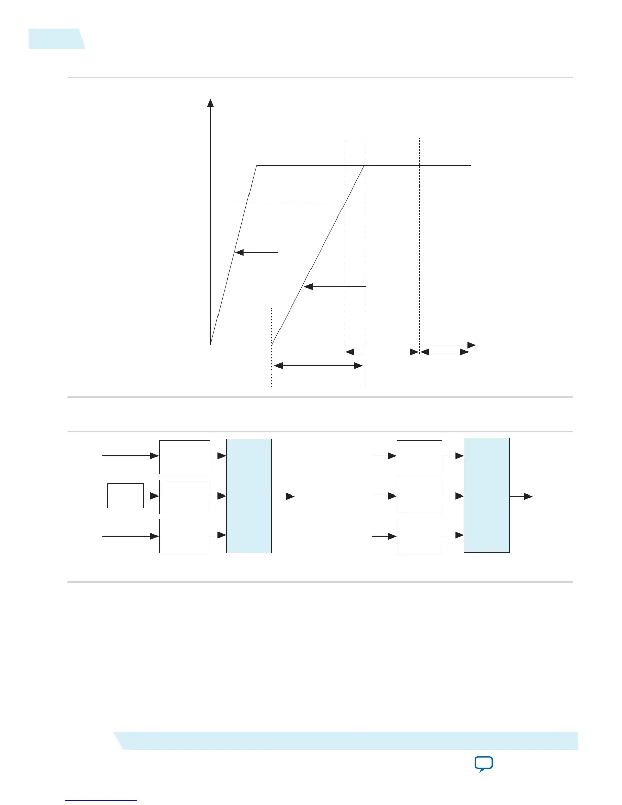
Figure 2-3: Relationship Between t
RAMP
and POR Delay
Time
POR trip level
Volts
POR delay
configuration
time
t
RAMP
first power
supply
last power
supply
Figure 2-4: Simplified POR Diagram for MAX 10 Devices
V
CCIO
Modular
Main POR
Main POR
V
CCA
V
CCIO
POR
V
CC
V
CC
POR
V
CCA
POR
V
CCIO
Modular
Main POR
Main POR
V
CCA
V
CCIO
POR
V
CC_ONE
V
CC
POR
V
CCA
POR
Voltage
Regulator
Single-Supply Device Dual-Supply Device
After the MAX 10 device enters user mode, the POR circuit continues to monitor the V
CCA
and V
CC
power supplies. This is to detect a brown-out condition during user mode. If either the V
CCA
or V
CC
voltages go below the POR trip point during user mode, the main POR signal is asserted. When the main
POR signal is asserted, the device is forced into reset state. V
CCIO
(3)
is monitored by the POR circuitry. In
the event of the V
CCIO
(3)
voltage drops during user mode, the POR circuit does not reset the device.
However, if you are using instant-on features, the POR circuit does monitor the VCCIO voltage drop for
up to 9 ms after the last power rail reaches its trip point.
2-6
Power Supplies Monitored and Not Monitored by the POR Circuitry
UG-M10PWR
2015.11.02
Altera Corporation
MAX 10 Power Management Features and Architecture
Send Feedback