Chapter 2: Board Components 2–13
General User Input/Output
September 2015 Altera Corporation MAX V CPLD Development Board Reference Manual
General User Input/Output
This section describes the user I/O interface to the CPLD, including the push-buttons
and status LEDs.
User-Defined Push-Button Switches
The development board includes two user-defined push-button switches. Board
references S1 (
USER_PB1
) and S2 (
USER_PB0
) are push-button switches that allow you to
interact with the MAX V CPLD device. There is no board-specific function for these
user-defined push-button switches.
Table 2–15 lists the user-defined push-button switch schematic signal names and their
corresponding MAX V CPLD device pin numbers.
Table 2–16 lists the user-defined push-button switch component reference and the
manufacturing information.
User-Defined LEDs
The development board includes two general purpose LEDs. Board references D7
(
USER_LED1
) and D8 (
USER_LED0
) are user-defined LEDs which allow status and
debugging signals to be driven to the LEDs from the CPLD designs loaded into the
MAX V CPLD device. There is no board-specific function for these LEDs.
Table 2–17 lists the user-defined LED schematic signal names and their corresponding
MAX V CPLD pin numbers.
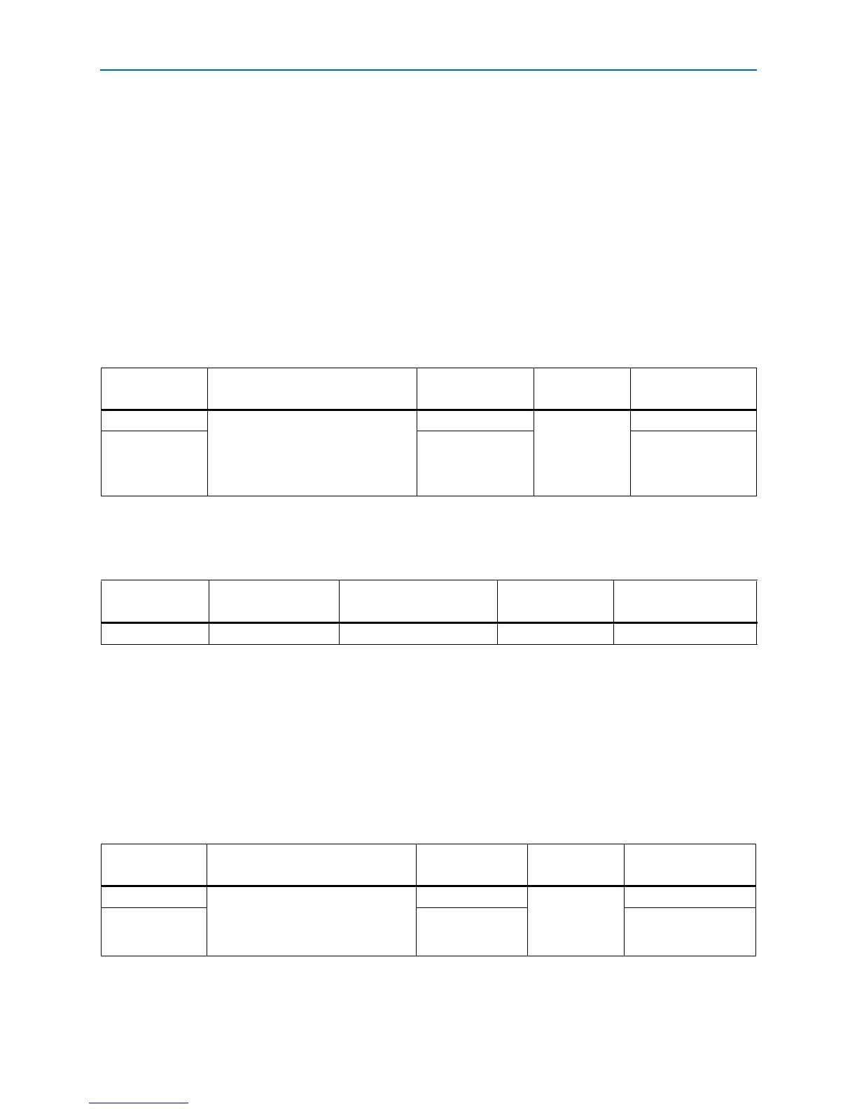
Table 2–15. User-Defined Push-Button Switch Schematic Signal Names and Functions
Board Reference Description
Schematic Signal
Name
I/O Standard
MAX V CPLD Device
Pin Number
S2 User-defined push-button switch.
When the switch is pressed and held
down, the device pin is set to logic 0;
when the switch is released, the
device pin is set to logic 1.
USER_PB0
3.3-V
M9
S1
USER_PB1
R3
Table 2–16. User-Defined Push-Button Switch Component Reference and Manufacturing Information
Board Reference Description Manufacturer
Manufacturer
Part Number
Manufacturer Website
S1, S2 Push-button switches Dawning Precision Co., Ltd. TS-A02SA-2-S100 www.dawning2.com.tw
Table 2–17. User-Defined LED Schematic Signal Names and Functions
Board Reference Description
Schematic
Signal Name
I/O Standard
MAX V CPLD Device
Pin Number
D8 User-defined LEDs.
Driving a logic 0 on the I/O port
illuminates the LED. Driving a logic 1
on the I/O port turns off the LED.
USER_LED0
3.3-V
P4
D7
USER_LED1
R1