EAV64334 06/2017 33
Multi drive Drive Systems Connection Diagram
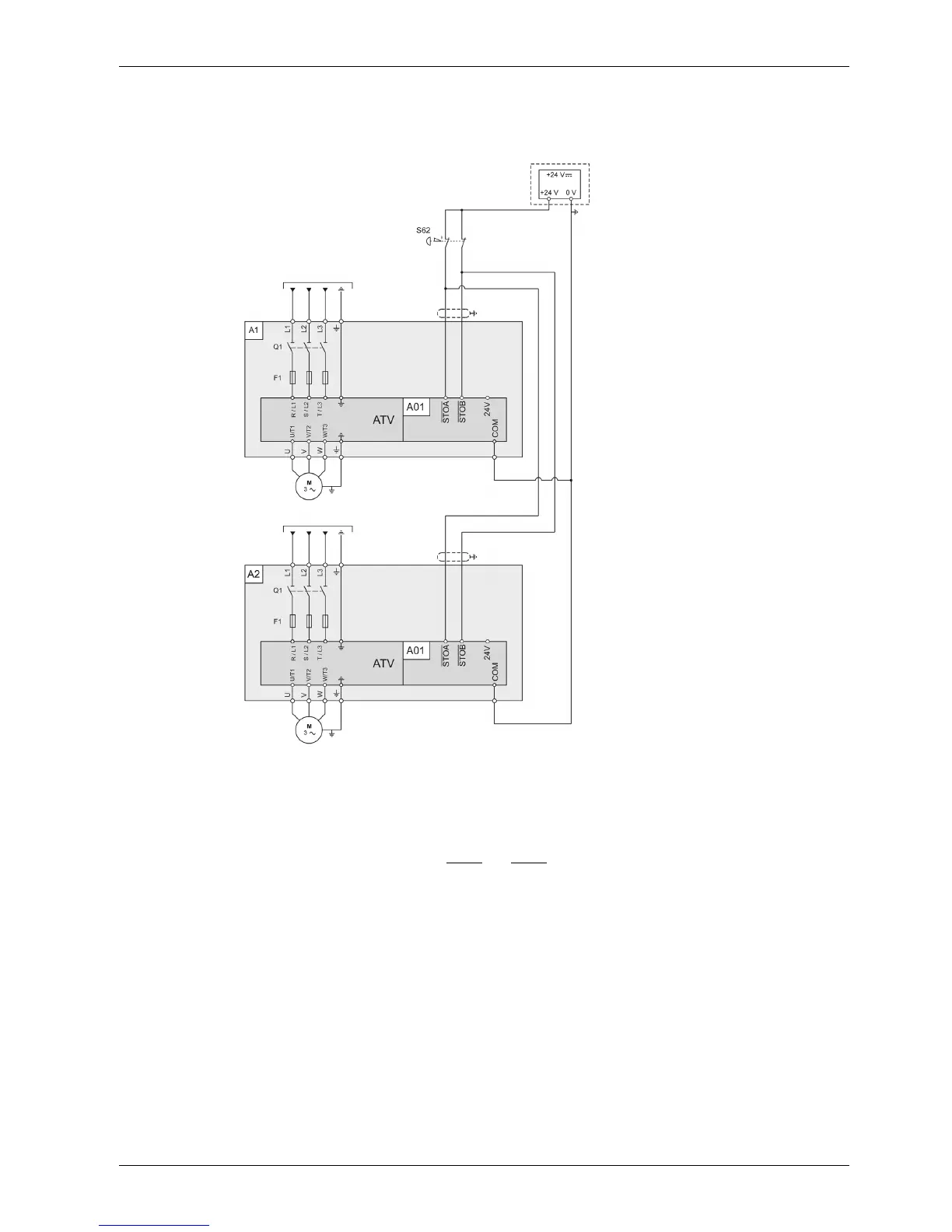
This connection diagram applies for multidrive Altivar Process Drive Systems configuration, without
options, according to IEC 61508 capability SIL 3, ISO 13849-1 category 3 PL e, IEC 60204-1 stop category
0 without protection against supply interruption or voltage reduction and subsequent rotation.
Legend:
A1, A2: Drive Systems enclosures with certified Drive Systems components assembly
A01: Control block of the Drive System
S62: External Emergency Stop button (not included within the certification)
NOTE: An EMERGENCY STOP is requested. This request leads to a category 0 stop. The power stage is
immediately disabled via the inputs STOA
and STOB of the safety function STO. Power can no longer be
supplied to the motor. If the motor has not yet stopped at this point in time, it coasts down in an uncontrolled
way (uncontrolled stop).