36 EAV64334 06/2017
Process System SF - Case 6
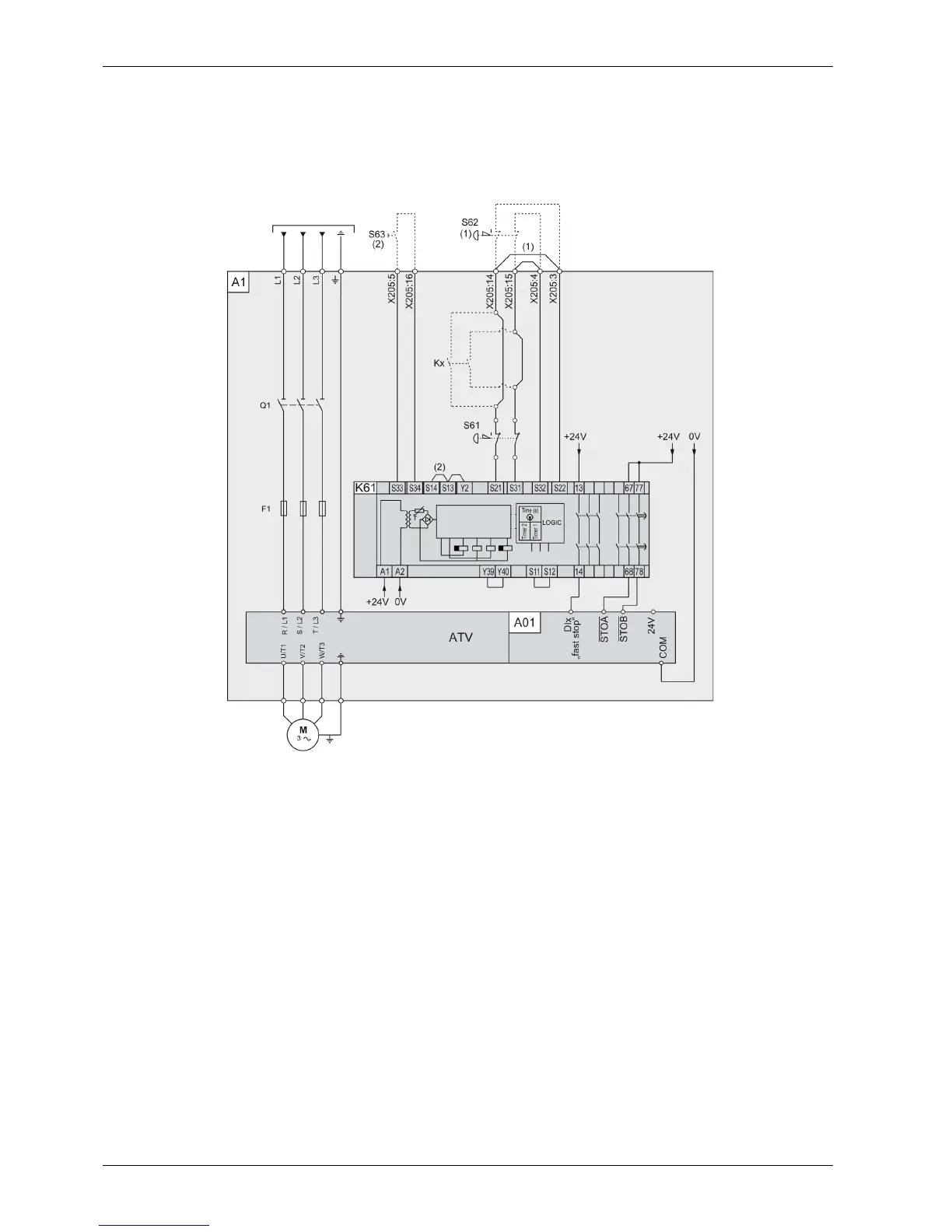
Single Drive Systems Connection Diagram with Option Safe Torque Off STO - SIL3 Stop category 1
This connection diagram applies for a single Altivar Process Drive Systems configuration, with option
VW3AP1503 (Safe Torque Off STO - SIL 3 Stop Category 1) according to IEC 61508 capability SIL 3, ISO
13849-1 category 3 PL e, IEC 60204-1 stop category 1.
Legend:
A1: Drive Systems enclosure with certified architecture, with built-in Drive Systems components
assembly and with option VW3AP1503.
A01: Control block of the Drive System
K61: Safety relay for monitoring the Emergency Stop circuit: Preventa XPS-ATR
S61: Emergency Stop buttons mounted in the enclosure door
DIx: Internal I/O set to “fast stop”
S62: External Emergency Stop button (not included within the certification)
(1): If S62 external emergency stop is installed, the wire link between terminals X205:14 and X205:3,
and between terminals X205:15 and X205:4 has to be removed.
Kx: optional additional contacts within the safety path (not included within the certification). These
contacts have to be taken into account separately for the safety path calculation.
S63: Manual reset button
(2): If a manual reset button is installed the wire link between the terminals S13/S14 on the safety relay
has to be removed.