EAV64334 06/2017 37
Example
An Emergency Stop is requested. This request leads to a stop category 1:
The function "fast stop" is immediately started (undelayed) via the digital input DIx (single-channel, not
monitored). Any active movement is decelerated via the adjusted ramp.
The power stage is disabled via the inputs STO_A and STO_B of the safety STO function after the delay
time set in the Emergency Stop Safety Module has elapsed. Power can no longer be supplied to the
motor. If the motor has not stopped yet when the delay time has elapsed, it coasts down in an
uncontrolled way (uncontrolled stop).
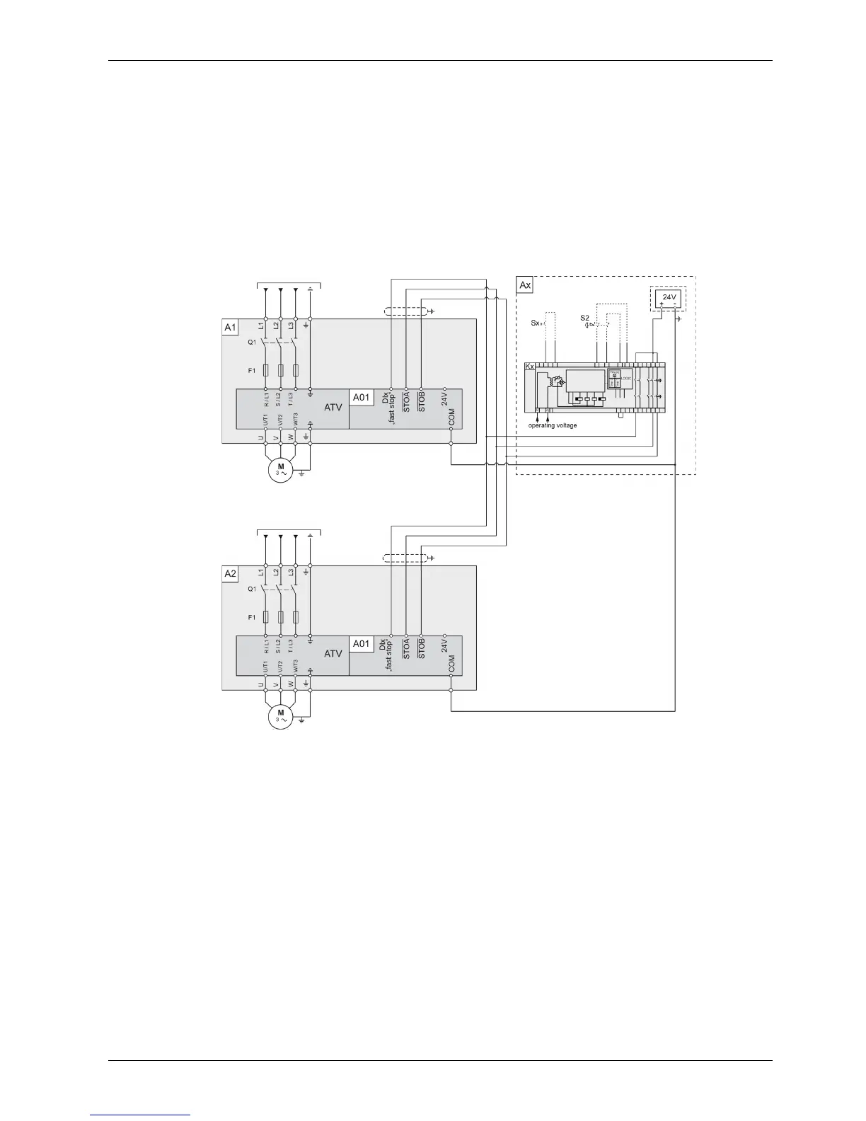
Multidrive Drive Systems Connection diagram with Safety Module
This connection diagram applies for a multidrive Altivar Process Drive Systems configuration with a safety
module stop category 1.
Legend:
A1, A2: Drive Systems enclosure without options (certified - see case 4), with certified Drive Systems
components assembly.
A01: Control block of the Drive System
Ax: External functional safety path (not included within the certification) with following components:
S2: External Emergency Stop button
Kx: Safety module
Sx: Manual reset button
Example
An Emergency Stop is requested if an Emergency Stop Safety Module, with stop category 1 is used. This
request leads to a stop category 1.
The function "fast stop" is immediately started (undelayed) via the digital input DIx (single-channel, not
monitored). Any active movement is decelerated via the adjusted ramp.
The power stage is disabled via the inputs STO_A and STO_B of the safety STO function after the delay
time set in the Emergency Stop Safety Module has elapsed. Power can no longer be supplied to the
motor. If the motor has not stopped yet when the delay time has elapsed, it coasts down in an
uncontrolled way (uncontrolled stop).
NOTE: The specified minimum current and the permissible maximum current of the relay outputs of the
Emergency Stop Safety Module must be observed.