34 EAV64334 06/2017
Process System SF - Case 5
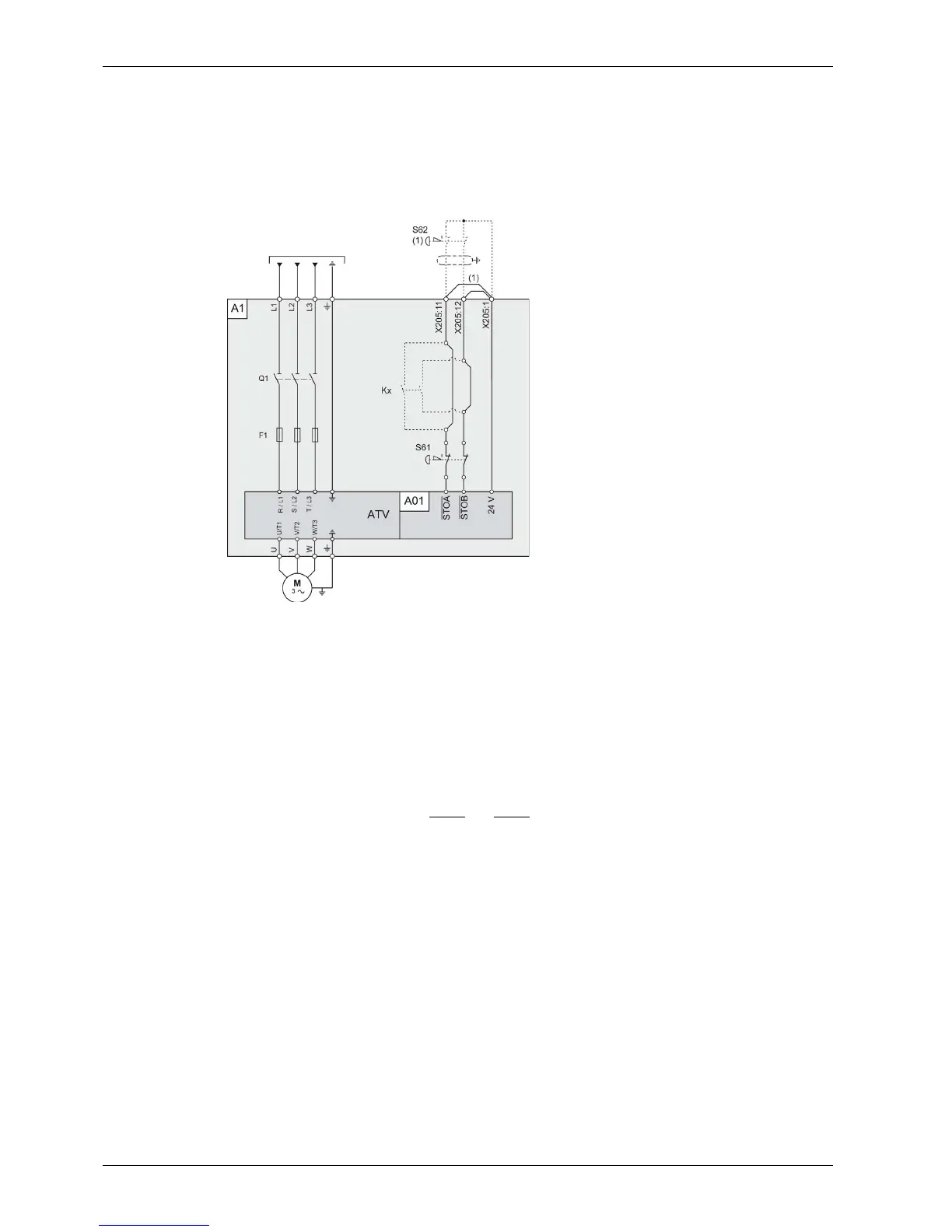
Single Drive Systems Connection Diagram with Option Safe Torque Off STO - SIL3 Stop category 0
This connection diagram applies for a single Altivar Process Drive Systems configuration, with option
VW3AP1502 (Safe Torque Off STO - SIL 3 Stop Category 0) according to IEC 61508 capability SIL3, ISO
13849-1 category 3 PL e, IEC 60204-1 stop category 0 without protection against supply interruption or
voltage reduction and subsequent rotation.
Legend:
A1: Drive Systems enclosure with certified architecture, with built-in Drive Systems components
assembly and with option VW3AP1502.
A01: Control block of the Drive System
S61: Emergency Stop button mounted in the enclosure door
S62: External Emergency Stop button (not included within the certification)
(1): If S62 external emergency stop is installed, the wire link between terminals X205:11 and X205:1,
and between terminals X205:12 and X205:1 has to be removed.
Kx: optional additional contacts within the safety path (not included within the certification). These
contacts have to be taken into account separately for the safety path calculation
NOTE: An EMERGENCY STOP is requested. This request leads to a category 0 stop. The power stage is
immediately disabled via the inputs STOA
and STOB of the safety function STO. Power can no longer be
supplied to the motor. If the motor has not yet stopped at this point in time, it coasts down in an uncontrolled
way (uncontrolled stop).