38 EAV64334 06/2017
Process System SF - Case 7
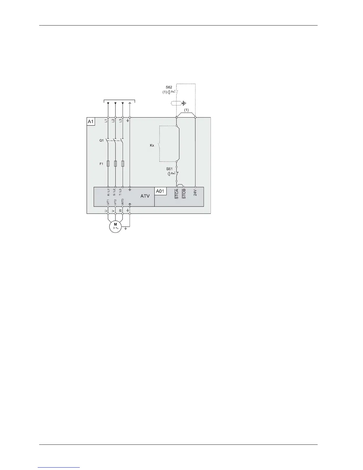
Single Drive Systems Connection Diagram for ETO
This connection diagram applies for a single Altivar Process Drive Systems configuration, within an
Engineered to Order (ETO) purchase order. The connection diagram applies according to IEC 61508
capability SIL 1, ISO 13849-1 category 1 PL c, IEC 60204-1 stop category 0 without protection against
supply interruption or voltage reduction and subsequent rotation.
Legend:
A1: Drive Systems enclosure with certified architecture for ETO with built-in Drive Systems components
assembly.
A01: Control block of the Drive System
S61: Emergency Stop button mounted in the enclosure door
S62: External Emergency Stop button (not included within the certification)
Kx: Optional additional contacts within the safety path (not included within the certification) These
contacts have to be taken into account separately for the safety path calculation.
(1): If S62 external emergency stop is installed, the wire link has to be removed.